


Chapter-wise Class 10 Science Questions and Answers Free PDF Download
Comprehending Class 10 Science Curriculum can be a bit challenging, but with the right resources, it becomes significantly easier. Vedantu’s NCERT solutions for Class 10 Science are designed to help you master the subject efficiently and effectively. Our NCERT solutions for class 10 Science strengthen your understanding of key concepts and cover everything you need.
 Table of Content
Download the PDF for Class 10 Science for the academic year 2025-26 to study at your convenience. These solutions provide detailed clarification that will help you understand both theoretical concepts and practical applications. A significant benefit of using these solutions is their alignment with the prescribed curriculum. You can also check the updated CBSE Class 10 Syllabus for Science, prepared by Vedantu Master Teachers.
FREE PDF Links for Chapter-wise NCERT Solutions Class 10 Science
Get access to chapter-wise NCERT Solutions for Class 10 Science from the links below and kick start your preparation for Class 10 Board exams.
The following Chapters have been removed from NCERT Class 10 Science for the Academic year 2025-26
Periodic Classification of Elements
Sources of Energy
Management of Natural Resources
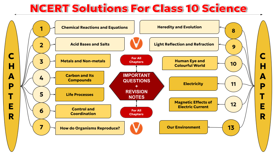
Below is the pictorial representation of the NCERT Science Class 10 syllabus for better understanding.
A Brief Overview of NCERT Solutions for Class 10 Science
NCERT Solutions for Class 10 Science provides detailed answers to all the questions from Chapter 1 to 13.
NCERT Class 10 Science Solutions provide clarity on fundamental concepts, theories, and formulas, making learning more effective and engaging.
The solutions are aligned with the revised CBSE curriculum of the academic year 2025-26
NCERT Class 10 Science solutions provides supplementary resources such as class notes, important concepts and other recommended books for further reference.


FAQs on NCERT Solutions For Class 10 Science - 2025-26
1. Are these NCERT Solutions for Class 10 Science updated for the latest 2025-26 CBSE syllabus?
Yes, all solutions provided are meticulously updated to align with the revised CBSE 2025-26 curriculum for Class 10 Science. This ensures that students focus only on the topics prescribed for the current academic year, including all new and modified content.
2. Do these solutions cover every single question from the official NCERT Class 10 Science textbook?
Absolutely. Our NCERT Solutions provide detailed, step-by-step answers for all in-text and exercise questions found in every chapter of the latest NCERT Class 10 Science textbook, ensuring comprehensive coverage.
3. How do these NCERT solutions explain the methodology for solving numerical problems in Physics and Chemistry?
For numericals, particularly in chapters like 'Light' and 'Electricity', the solutions provide a complete breakdown of the correct method. This includes:
- Identifying the given data from the problem statement.
- Stating the relevant formula or scientific law required.
- Showing the step-by-step substitution and calculation.
- Concluding with the final answer and the correct SI units, as per the CBSE marking scheme.
4. What makes these Class 10 Science NCERT Solutions a reliable resource for board exam preparation?
These solutions are crafted by subject matter experts to guarantee accuracy and conceptual clarity. Their reliability comes from:
- A focus on the step-by-step methodology that helps in understanding the logic behind answers.
- Strict adherence to the latest CBSE syllabus and exam pattern.
- Clear explanations for complex theories, reactions, and principles to build a strong foundation.
5. Why is it more effective to understand the method in these solutions than to simply memorise answers?
Memorising answers is a flawed strategy. Understanding the problem-solving method through these solutions is crucial because it helps you:
- Apply core concepts to unfamiliar or higher-order thinking skills (HOTS) questions in exams.
- Build a robust conceptual foundation in science for future studies (Class 11 and 12).
- Develop analytical skills instead of relying on rote learning, which is essential for scoring well in Science.
6. Are the diagrams and chemical equations in the solutions presented according to CBSE standards?
Yes. All diagrams are drawn clearly with accurate, neat labels. All chemical equations are correctly balanced, and necessary reaction conditions (like catalysts or temperature) are specified, teaching you how to write answers that meet the board's expectations for full marks.
7. How can using these NCERT solutions improve my final board exam score?
Consistent use of these solutions helps you master the NCERT textbook, which is the cornerstone of the CBSE board exam. By learning the correct step-wise approach for different types of questions, you can avoid common errors, manage your time effectively during the exam, and present your answers with clarity, all of which contribute to achieving a higher score.
8. Do the solutions cover all three branches of Science for Class 10?
Yes, the NCERT Solutions cover all prescribed chapters from Physics, Chemistry, and Biology. This includes detailed answers for chapters like 'Life Processes' (Biology), 'Carbon and its Compounds' (Chemistry), and 'Magnetic Effects of Electric Current' (Physics), providing a single, comprehensive resource.
9. Are solutions provided for chapters removed from the syllabus for the 2025-26 session?
No. To ensure students focus their efforts effectively, these NCERT solutions are strictly based on the current 2025-26 NCERT syllabus. Chapters that have been removed by CBSE, such as 'Periodic Classification of Elements', are not included in this resource.