


An Overview of Class 12 Physics To Determine Resistance Per Cm Of A Given Wire By Plotting A Graph Of Potential Difference Versus Current Experiment
A conductor is made of infinite atoms, each of these have a nucleus as well as orbiting electrons. When an external field is applied to these electrons, they drift leading to the origin of current. When these electrons encounter heavy nuclei, they collide and slow down. This opposition to current is called resistance $(R)$. The resistance is represented by the formula $R \ = \ \rho \frac{L}{A}$ where, $\rho$ is specific resistance which depends only on the material of the conductor and $L$ is length whereas $A$ is cross-section area which define the dimensions of the conductor.
It also changes with change in temperature. It increases with temperature and can be predicted by the formula $R_T \ = \ R_0 [1 \ + \ \alpha \Delta T]$
Where, $R_T$ is resistance at given temperature, $R_0$ is resistance at absolute zero, $\alpha$ is the temperature coefficient and $\Delta T$ is the change in temperature.
Table of Contents
Aim
Apparatus required
Theory
Procedure
Observations
Result
Precautions
Lab Manual Questions
Viva Questions
Practical Based Questions
Aim
To determine resistance per cm of a given wire by plotting a graph of potential difference versus current
Apparatus Required
Wire of unknown resistance $(\sim 10 \Omega)$
Battery eliminator or an accumulator $(0 \ - \ 3V)$ or two dry cells $(1.5 V \ each)$
Voltmeter $(0 \ - \ 5 V)$
Milliammeter $(0 \ – \ 500 mA)$
Rheostat
Plug key
Connecting wires
Piece of sandpaper
Theory
According to Ohm's law, if a conductor's physical state doesn't change, the electric current flowing through it is directly proportional to the potential difference at its ends.
If $I$ is the current flowing through a conductor due to a potential difference $V$ applied across its ends, then by Ohm’s law we have:
$V\propto I$
And hence, $V=RI$ …..(1)
Where, $R$ is the constant of proportionality, known as the electrical resistance of a conductor. It is the opposition to the flow of electrons in a conductor, due to the presence of constituent atoms. $R$ is represented in ohms $(\Omega)$ if $V$ is expressed in volts and $I$ in Amperes. The conductor's material and dimensions have an impact on the resistance $R$. The resistance for a wire with a uniform cross section relies on the length $l$ and the cross-sectional area $A$. The conductor's temperature is another factor. The resistance at a particular temperature can be represented by
$R \ = \ \rho \times \frac{l}{A}$ …..(2)
Where, $\rho$ is specific resistivity and depends on the material of the conductor.
Using (1) and (2), we have,
$V \ = \ \left ( \rho \frac{l}{A} \right ) \times \ I$ …..(3)
Comparing (3) with equation of graph with straight line slope $y = mx$ we can deduce that if a graph of $V$ versus $I$ is plotted, with $V$ on the y-axis and $I$ on the x-axis, then the slope of the graph will give the value of resistance $R$.
Procedure
With the use of sandpaper, clean the connecting wires' ends to remove any insulating coating.
Connect the circuit as shown in the diagram.
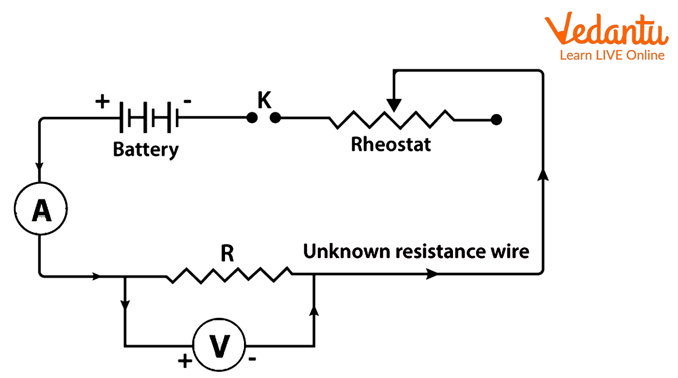
Circuit diagram
Adjust the voltmeter and milliammeter such that their needles coincide with the zero mark. This will ensure error free reading.
Slide the rheostat contact to one of its extreme ends, after inserting the key $K$, to ensure that the least amount of current is going through the resistance wire. Now note the readings of the voltmeter and the milliammeter.
Unplug the key $K$ and wait for the wire to cool. Shift the rheostat to decrease resistance and increase potential applied. Now plug in the key $K$ and note the new voltmeter and milliammeter readings.
Repeat the above step at least four times, with different rheostat settings and note the readings each time.
Observation
Ammeter range-
Least count of ammeter-
Range of voltmeter-
Least count of voltmeter-
Length of the given wire-
Least count of meter scale-
Observation Table
Result
Plot a graph between $V$ and $I$, with $V$ on the y axis and $I$ on the y axis. By Ohm’s law, the slope of the graph will give value of resistance of wire $R$

Graph for Ohm’s law
With the help of length of wire $l$, we can calculate resistance per centimeter by $\frac{Resistance \ (R)}{Length \ of \ wire \ (l)}$
Error in reading:
$ \frac{\Delta R}{R} = \frac{\Delta V}{V} + \frac{\Delta I}{I}$
Therefore,
The resistance of the wire is
The error in measurement is
The resistivity of the wire is
Precautions
The circuit should have the voltmeter connected in parallel and the ammeter connected in series.
Make sure that the positive terminal is where current enters and the negative terminal is where it exits.
The key should only be inserted when making observations since a high current flowing through will heat the wire unnecessarily and alter its resistance.
It is important to be aware of and eradicate any measurement equipment of zero error, including voltmeters, ammeters, and meter scales. Voltmeters and ammeters may be adjusted by turning the screw at the base of the needle with the use of a screwdriver.
Lab Manual Questions
1. It is said to always connect an ammeter in series and a voltmeter in parallel with the circuit. Why? If connected in a reverse arrangement, will they still give correct readings?
Ans: The ammeter reads the current whereas the voltmeter reads the voltage. The current for two electrical elements in series is the same, therefore the ammeter must be connected in series. Similarly, the voltmeter is connected in parallel since two electrical elements connected in parallel have the same potential difference across their ends. If they are connected in reverse arrangement, they won’t give correct readings.
2. Why are copper wires typically used to connect various electrical circuit components?
Ans: Copper is an excellent conductor of electricity. Therefore, it is used to make connecting wires to minimize resistance through the circuit.
3. How does the length of wire affect its resistance, when its diameter is kept constant?
Ans: The resistance is represented by the formula $R \ = \ \rho \frac{L}{A}$ where, $\rho$ is specific resistance which depends only on the material of the conductor and $L$ is length whereas $A$ is cross-section area which define the dimensions of the conductor.
Therefore, if the diameter is kept constant, $A$ becomes constant. The relation between resistance $R$ and length $l$ hence becomes direct.
4. What happens if the circuit is left with the current flowing continuously for a prolonged period? Why?
Ans: If the circuit is left with the current flowing continuously for a prolonged period, the current flowing through wires produces heat and increases their temperature. Due to this, the resistance of wire also increases.
Viva Questions
1. The length of two identical wires made of the same material is the same. While the other has a non-circular cross section of the same area A, the first has a circular cross section of that area. Will they have comparable resistances?
Ans: They will have the same resistances irrespective of the shape of the cross section.
2. What are the possible sources of error?
Ans: Few possible sources of error include:
The cross-sectional area of the wire may not be uniform.
The resistance wire's length should be measured between the voltmeter's two terminals. If included, the lengths of ends looped around the voltmeter's terminals would introduce measurement error.
The wires are heated and thus provide some resistance.
3. What is the use of a rheostat in the circuit?
Ans: It is used to vary the resistance in the circuit and obtain multiple readings for the same set up.
4. Why is the voltmeter connected in parallel?
Ans: This is because it measures potential difference and the potential difference across to points in parallel is the same.
5. What factors affect the resistance of a conductor?
Ans: The resistance of a conductor is dependent upon its length, cross-section area, its material and temperature.
6. How does resistance vary with temperature for conductors and semiconductors?
Ans: The resistance of a conductor increases with temperature ohmically whereas it decreases for the semiconductor up to a certain point, with increase in temperature.
7. Why is the ammeter connected in series?
Ans: This is because the ammeter measures current and current for two electrical components in series is the same.
8. What are the reciprocals of resistance and resistivity? What is its significance?
Ans: The reciprocals of resistance and resistivity are conductance and conductivity. They represent the material's ability to conduct the flow of current.
9. Is Ohm’s law valid for all types of devices? Why or why not?
Ans: No, Ohm’s law is valid only for certain devices which are known as Ohmic devices. This is because the variation of potential difference and current is not constant for all electrical devices.
10. Define electric current. What is its SI unit?
Ans: The flow of charge $(q)$ per unit time $(t)$ through a point is known as electric current. It can be represented as $\frac{q}{t}$. Its SI unit is Ampere.
Practical Based Questions
The current $I$ versus voltage $V$ plot of a certain electronic device is given below. The device is

Graph for Q1
A semiconductor
A conductor that obeys Ohm’s law
A superconductor
An insulator
Answer: (b)
In a circuit, a battery of terminal voltage $V$ is connected to a net resistance $R$. If $I$ current is drawn from the battery, then the power consumed by the battery is given by
$VI$
$\frac{V^2}{R}$
$I^2 R$
All of these
Answer: (d)
When an electric heater receives an electric current of $4A$ from the source, the potential difference across its ends is $60V$ . If the potential difference is increased to $127.5 V$ , then what will be the current received by the heater?
$24 \ A$
$10 \ A$
$8.5 \ A$
$12 \ A$
Answer: (c)
Ohm’s law is applicable to
Silicon carbide
Zener diode
Voltage regulator tubes
Copper
Answer: (d)
According to Ohm’s law, which of the following is constant?
$VQ$
$\frac{I}{V}$
$IT$
$\frac{V}{I}$
Answer: (d)
Ohm’s law can also be taken as a statement for
Conservation of energy
Conservation of electric charge
Conservation of angular momentum
Non-conservation of momentum of the flowing charge
Answer: (a)
The potential difference between two points of a wire carrying $2 \ A$ current is $0.1 \ V$. The resistance of the wire is
$0.05 \ \Omega$
$0.5 \ \Omega$
$5 \ \Omega$
$0.25 \ \Omega$
Answer: (a)
Volt per ampere is also called
Ohm-meter $(\Omega m)$
Joule
Ohm $(\Omega)$
Mho $(Ohm^{-1})$
Answer: (c)
In a laboratory, an experiment goes with resistance to show it follows Ohm’s law. Which of the following statement(s) is required for true results
Temperature remains constant
The graph between $V$ and $I$ is a straight line
$I \ = \ V \times R$
Both (a) and (b)
Answer: (d)
Which one of the following devices is non-Ohmic?
Conducting copper coil
Electric heating coil
Semiconductor diode
Rheostat
Answer: (c)
Summary
The opposition to the flow of electrons is resistance. Ohm's law explains the linear variation of a potential difference $V$ across the ends of a conductor, with current $I$ flowing through it. The constant defined here is resistance $R$, which depends on the material and dimensions of a conductor. Resistance of conductors is also dependent on temperature, and it increases with temperature. By Ohm’s law, one can also find the resistance by plotting a $V-I$ graph.
FAQs on Class 12 Physics To Determine Resistance Per Cm Of A Given Wire By Plotting A Graph Of Potential Difference Versus Current Experiment
1. What is the most important step to accurately determine the resistance per cm of a wire during a CBSE Class 12 board examination experiment?
The most important step is to plot an accurate graph of potential difference (V) versus current (I), ensuring all readings are taken after waiting for the wire to cool and with proper zero-error adjustments for ammeters and voltmeters. The slope of the resulting straight line directly gives the value of resistance (R), which can then be divided by the length of the wire to get resistance per cm.
2. State and explain the formula used to calculate resistance per unit length for a wire and mention its relevance in board exam questions.
The formula is Resistance per unit length = R/l, where R is the resistance obtained from the slope of the V-I graph and l is the measured length of the wire. This calculation is fundamental for scoring in 5-mark experimental questions in CBSE Physics, as it tests both understanding and data handling skills.
3. What precautions must be taken to avoid common errors that affect marking in Class 12 Physics practical board exams for resistance measurement?
Key precautions include:
- Connect the ammeter in series and the voltmeter in parallel as per the circuit diagram to avoid marking penalties.
- Insert the key only when taking readings to prevent wire heating and inaccurate resistance.
- Remove any coating from wire ends with sandpaper and check for zero errors in measuring instruments.
4. Why is it essential to keep the temperature of the wire constant during the resistance experiment in board assessments?
It is essential to maintain a constant temperature because an increase in temperature increases the wire’s resistance, which can lead to incorrect results. Board examiners assess if students recognize this and take steps such as unplugging the key between readings to avoid temperature-induced errors.
5. How does the error in the measurement of potential difference and current affect the calculation of resistance per cm in exam situations?
Any error in measuring V (potential difference) or I (current) directly affects the calculated value of R as R = V/I. For board marks, the propagation of error must be managed by using the formula ΔR/R = ΔV/V + ΔI/I and ensuring precise instrument readings, as calculation mistakes are often penalized in marking schemes.
6. What marking weightage is typically assigned to the experiment 'To Determine Resistance Per cm of a Given Wire' in the CBSE 2026–27 Physics board exam?
This practical experiment generally carries 4 to 5 marks in the board practical exam. Marks are distributed for correct setup (circuit diagram), observations (tabulated readings), graph plotting, calculations (including resistance per cm), and viva/principle-based questions.
7. What are examiners looking for in the V-I graph plotted during the Physics board practical?
Examiners expect a straight-line V-I graph passing through the origin, as it verifies Ohm's law and the accurate functioning of the apparatus. Deviations or non-linear plots may result in loss of marks for improper technique or setup issues.
8. Which conceptual traps should be avoided to secure full marks in board questions about resistance determination?
Avoid these common errors:
- Confusing series and parallel circuit connections for voltmeter and ammeter
- Not accounting for changes in resistance due to wire heating
- Neglecting to record the correct length of the wire between potential measurement points
9. How would increasing the thickness of the wire while keeping its length unchanged affect the resistance per cm, and why might this be a high-order board question?
Increasing the thickness (cross-sectional area, A) decreases the resistance, according to R = ρl/A. For resistance per cm, the decrease in R leads to a proportionally lower R/l. This type of analysis assesses deeper conceptual understanding, a key criterion for high-mark questions.
10. In the context of board exams, why is Ohm’s law not applicable to all materials tested in school laboratories?
Ohm’s law is only valid for Ohmic materials (metals with linear V-I characteristics at constant temperature). Non-Ohmic materials like diodes or semiconductors show non-linear V-I graphs, a point that examiners use to test conceptual clarity in viva or HOTS (higher-order thinking skills) questions.