


An Overview of Class 12 Physics Conversion Of Galvanometer Into A Voltmeter Of Required Range Experiment
A galvanometer is a device generally used to measure the magnitude and direction of current in a circuit. It is a very sensitive device that can measure only small currents. It may get damaged if we pass a current through a galvanometer more than the specified amount. The maximum current that can be passed through a galvanometer is the full-scale deflection current.
To measure the potential difference in an appliance, we need a device known as a voltmeter. This device is always connected in parallel with the appliance.
Table of Contents
Aim
Apparatus Required
Theory
Procedure
Observations
Result
Precautions
Lab Manual Questions
Viva Questions
Practical Based Questions
Aim
To convert the given galvanometer (of known resistance and figure of merit) into a voltmeter of desired range and to verify the same.
Apparatus Required
A galvanometer
Key and battery
Sandpaper
A rheostat and connecting wires
A voltmeter of 0-3V range
Resistance box
Theory
Galvanometer can be converted into a voltmeter by connecting suitable high resistance in series with it, so that very small current flows through the galvanometer. A voltmeter should have high resistance so that current flowing through it is negligible.
Now, we will calculate the required series resistance to convert galvanometer into voltmeter.
According to Ohm’s law,
$V = {I_g}\left( {G + R} \right)$ … … …(i) (From the figure given below)
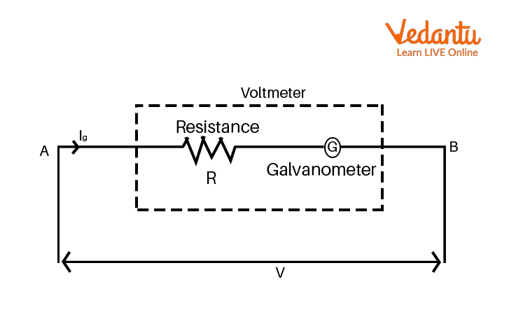
Conversion of galvanometer to a voltmeter
From this equation, we can say that potential difference is directly proportional to the current which is flowing through the galvanometer.
From equation (i), we can write,
$\dfrac{V}{{{I_g}}} = G + R$
So, $R = \dfrac{V}{{{I_g}}} - G$
This is the formula which we can use to find the value of high resistance.
Where,
$R$ is high resistance which is connected in series with the galvanometer
$V$ is the maximum voltage to be measured
$G$ is the resistance of the given galvanometer
${I_g}$ is the full scale deflection current and this is the maximum current that can flow through the galvanometer.
${I_g} = nk$ Where, $k$ is the figure of merit and $n$ is the number of divisions in the galvanometer scale.
Procedure
First of all, we need to connect the resistance box in series combination with the galvanometer and take out the plugs of resistance R.
Conversion Of Galvanometer Into Voltmeter
Now, the given galvanometer can be used as a voltmeter of range V volts.
Now, we should take out the plugs of calculated resistance R from the resistance box. Then, insert the key K and adjust the movable contact of the rheostat such that the deflection of the galvanometer becomes maximum. Now, note the readings of the galvanometer and voltmeter.
We need to convert the galvanometer reading into volts. Carefully observe the difference in the readings. This difference between voltmeter reading and galvanometer reading will give us the error.
By moving the variable contact of rheostat, take at least 5 readings covering the whole range of voltmeter from 0-3 Volts and record your observations.
Observations
Least count of the galvanometer converted into voltmeter is L.C. = \[\dfrac{V}{n}\] = _____
Resistance of the given galvanometer $G$ = _____
Figure of merit $k$ = _____
Number of divisions in the galvanometer scale $n$ = _____
Current for full scale deflection ${I_g} = nk$ = _____
Range of conversion $V$ = _____
Resistance to be placed in series with the galvanometer $R = \dfrac{V}{{{I_g}}} - G$ = _____
Result
From this experiment, we have found that,
The calculated value of series resistance which we calculated using the formula and by performing this experiment, we found that the observed value of series resistance is equal to the calculated value of series resistance.
The potential difference's actual and measured value is very small. So, conversion is verified.
Precautions
We need to calculate resistance accurately.
In this experiment, the rheostat should be used as a potential divider.
For verification, we should use the same range conversion voltmeter.
Lab Manual Questions
1. What is a voltmeter?
Ans: Voltmeter is a device generally used to measure the potential difference between two points of the electric circuit.
2. How can we change the range of the voltmeter?
Ans: We can increase the range of the voltmeter by increasing its resistance. This can be done by connecting an additional resistance in series with it.
3. How can we change the voltmeter into a millivoltmeter?
Ans: By decreasing its resistance, we can change the voltmeter into a millivoltmeter because the resistance of the millivoltmeter is much less than that of the voltmeter.
Viva Questions
1. What should be the resistance of a voltmeter in this experiment?
Ans: In this experiment, the resistance of a voltmeter should be high.
2. How can we change an ammeter into a voltmeter?
Ans: By putting a suitable high resistance in series with an ammeter, we can change an ammeter into a voltmeter.
3. How can we convert a voltmeter into an ammeter?
Ans: By shunting the voltmeter with low resistance, we can convert voltmeter the into an ammeter.
4. What is the resistance of an ideal voltmeter?
Ans: The ideal resistance of an ideal voltmeter is infinity.
5. What is the use of a shunt?
Ans: Shunt protects galvanometer from damage from high voltage and current.
6. Can we use a galvanometer to measure heavy currents?
Ans: No, we can not use a galvanometer to measure heavy currents.
7. On which principle does a galvanometer work?
Ans: Galvanometer works on the principle of converting electrical energy into mechanical energy.
8. How can we convert a galvanometer into a voltmeter?
Ans: After deciding the range of the voltmeter to be designed, we find the value of high resistance to being connected in series with galvanometer resistance. This combination will then act as a voltmeter.
Practical-Based Questions
Which instrument can be used to measure electric current?
Galvanometer
Voltameter
Tube tester
Voltmeter
Ans: Option A - Galvanometer
A device which measures voltage, current and resistance is called a:
Resistor
Voltmeter
Screwdriver
Multimeter
Ans: Option D - Multimeter
Current is measured in
Amperes
Voltage
Ohms
Watts
Ans: Option A - Amperes
In an ammeter, the shunt resistance is usually _____ the metre resistance.
Equal to
Greater than
Less than
Greater than or equal to
Ans: Option C - Less than
What physical quantity does the voltmeter measure?
Voltage
Magnetic field
Volume
Temperature
Ans: Option A - Voltage
We can use a milliammeter as
A fuse
An ammeter
An electric field
None of the above
Ans: Option B - An ammeter
_____ voltmeter has the least power consumption.
Induction type
Moving coil type
Hot wire type
Electrostatic type
Ans: Option D - Electrostatic type
The internal resistance of a voltmeter must be high so that
Maximum current can pass through it
Minimum current passes through the meter
Accuracy becomes high
It can measure magnetic field
Ans: Option B - Minimum current passes through the meter
The main function of a shunt in an ammeter is to
Increase the specific resistance of the ammeter
Increase the resistance of the ammeter
Bypass the current
Increase the sensitivity of the ammeter
Ans: Option C - Bypass the current
An ammeter is a
Integrating instrument
Absolute instrument
Secondary instrument
Recording instrument
Ans: Option C - Secondary instrument
Conclusion
From the above experiment,
We have found that the value of calculated series resistance which we calculated using the formula $R = \dfrac{V}{{{I_g}}} - G$ is equal to the value of resistance which we found by performing this experiment. So, the calculated value and observed value are the same.
We can also conclude that the difference in actual value and the measured value of the potential difference is very small and hence conversion is perfect.
So, by performing this experiment, we converted the galvanometer into a voltmeter of desired range by connecting a very high resistance in series with the galvanometer.
FAQs on Class 12 Physics Conversion Of Galvanometer Into A Voltmeter Of Required Range Experiment
1. How is a galvanometer converted into a voltmeter for a specific range as per the CBSE Class 12 syllabus?
To convert a galvanometer into a voltmeter capable of measuring a desired voltage range (V), a very high resistance (R) is connected in series with the galvanometer coil. This high series resistance limits the current to the galvanometer's full-scale deflection current (I_g). The entire setup is then connected in parallel across the component whose potential difference needs to be measured.
2. What is the derivation for the high resistance needed to convert a galvanometer into a voltmeter? This is an important 3-mark question.
Let G be the galvanometer resistance and I_g be the current for full-scale deflection. To convert it to a voltmeter of range V, a high resistance R is connected in series.
The total resistance of the voltmeter becomes (R + G).
Applying Ohm's law to the entire setup:
V = I_g (R + G)
V / I_g = R + G
Therefore, the required high resistance is R = (V / I_g) - G. This is the required expression for the series resistance.
3. Why must a very high resistance be connected in series with a galvanometer to make a voltmeter?
A high resistance is connected in series for two critical reasons:
- To protect the galvanometer: A galvanometer is a very sensitive instrument. The high series resistance limits the current flowing through it to a safe value, preventing the coil from being damaged by high voltages.
- To ensure accuracy: A voltmeter is connected in parallel. To measure the true potential difference, it must draw a negligible amount of current from the main circuit. A high resistance ensures that the voltmeter does not significantly alter the circuit's original conditions, leading to a more accurate reading.
4. What is an ideal voltmeter and why is its resistance considered infinite?
An ideal voltmeter is a theoretical instrument that can measure the potential difference between two points without drawing any current from the circuit. For it to draw zero current (I=0), its resistance must be infinite, as per Ohm's law (V=IR). In reality, constructing a voltmeter with infinite resistance is impossible, but practical voltmeters are designed with extremely high internal resistance to closely approximate this ideal behaviour.
5. What are the key differences between a voltmeter and an ammeter for board exams?
The key differences frequently asked in exams are:
- Function: A voltmeter measures potential difference (voltage), while an ammeter measures electric current.
- Connection: A voltmeter is always connected in parallel to a component, whereas an ammeter is always connected in series within the circuit.
- Resistance: A voltmeter has a very high internal resistance to draw minimal current. An ammeter has a very low internal resistance to not obstruct the current flow.
6. Why can't a galvanometer be used directly to measure voltage in a circuit?
A galvanometer cannot be used directly as a voltmeter for two main reasons:
- Low Resistance: It has a very low coil resistance. If connected in parallel, it would act like a short circuit, drawing a large current and drastically changing the potential difference it is meant to measure.
- High Sensitivity: It is designed to detect very small currents. Even a small voltage would drive a large current through it, causing the pointer to deflect beyond its scale and potentially damage the coil.
7. How does connecting a voltmeter impact the circuit it is measuring, and why is a higher resistance voltmeter better?
When a voltmeter is connected in parallel, it provides an additional path for current, which slightly lowers the overall resistance of that part of the circuit. This phenomenon is called the loading effect. It causes the measured voltage to be slightly lower than the actual voltage. A voltmeter with a higher internal resistance draws less current from the main circuit. This minimises the loading effect and results in a more accurate measurement of the true potential difference.
8. What are the essential precautions for the CBSE experiment on converting a galvanometer to a voltmeter?
Key precautions for this experiment include:
- The value of the series resistance calculated should be accurately set in the resistance box.
- All electrical connections must be tight and clean to avoid introducing extra resistance.
- The key in the circuit should be plugged in only while taking readings to prevent heating of the galvanometer coil, which could change its resistance.
- Ensure the pointers of the galvanometer and voltmeter are at the zero mark before starting the experiment.