


All About XNOR Gate and How Does It Work in Digital Electronics?
The XNOR gate is a digital logic gate that performs the exclusive-NOR operation. Its output becomes 1 when both inputs are the same, either both 0 or both 1, and becomes 0 when the inputs are different.
Because of this behavior, the XNOR gate is widely used as a similarity checker or equality detector in digital circuits. It is also known as the equivalence gate or material biconditional in logic.
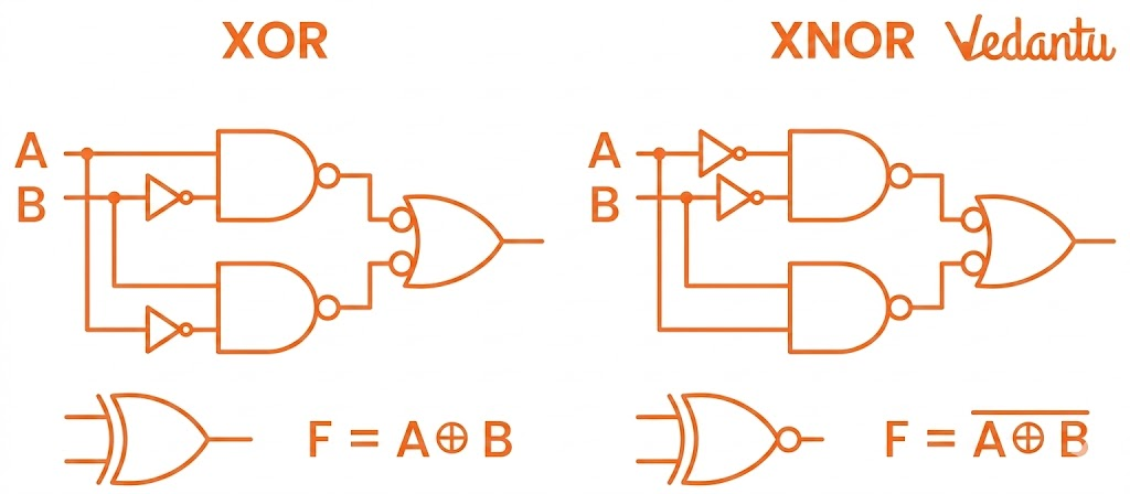
One important way to understand the XNOR gate is through its relation to the XOR gate. An XNOR gate is simply the complement of an XOR gate. So, if an XOR gate tells us when inputs are different, the XNOR gate tells us when inputs are equal. In symbolic form:
XNOR Gate = XOR Gate + NOT Gate
The XNOR operation is sometimes represented by the symbol ⊙. The gate is also called the equivalence gate, because it checks whether two logic conditions are equivalent.
XNOR Gate Symbol
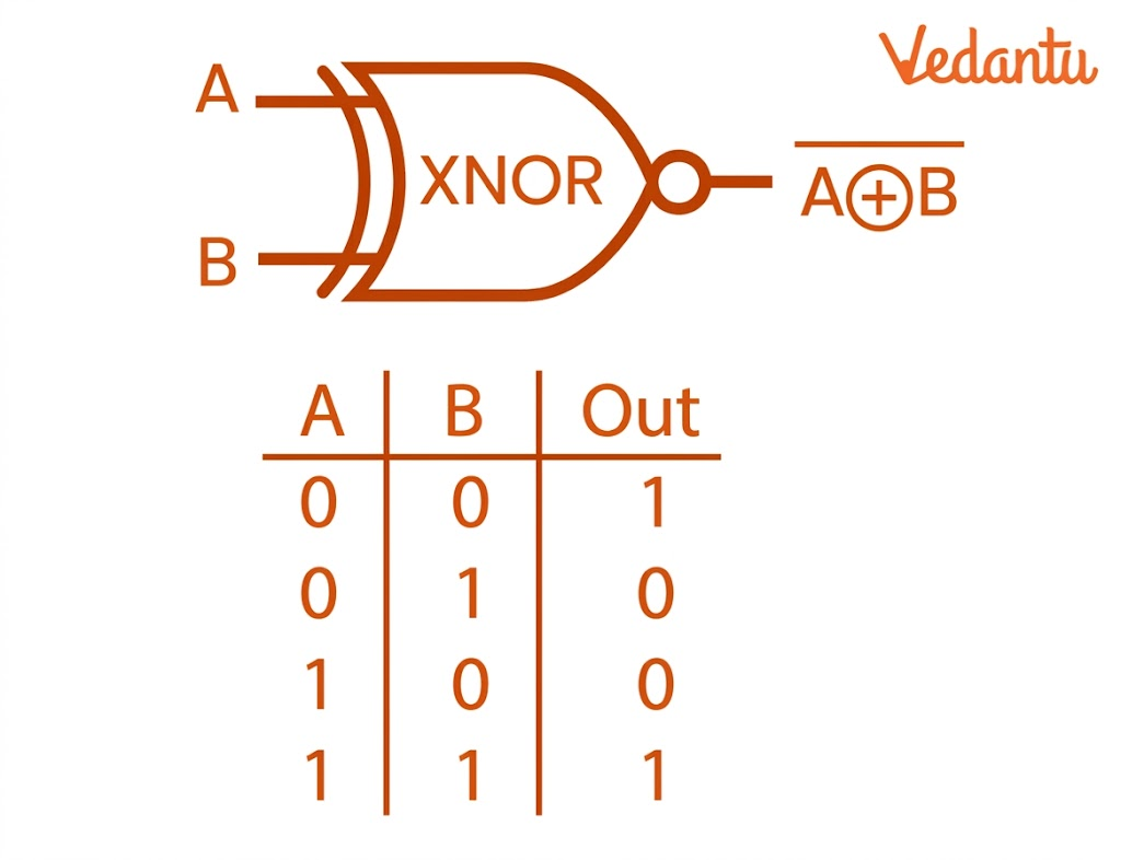
The xnor gate symbol looks similar to the XOR gate symbol, but with an additional small circle (inversion bubble) at the output. This bubble indicates logical negation. Since the XNOR gate is the inverse of the XOR gate, the symbol directly reflects that relationship.
In a standard symbol:
there are two inputs, usually labelled A and B
there is one output, usually labelled Y
the output line ends with a small circle, showing inversion
So, when you see an XOR-shaped symbol with a bubble at the output, you can identify it as an XNOR gate.
XNOR Gate Circuit Diagram
An xnor gate circuit diagram can be made in several different ways. Since the XNOR gate is not always available as a direct primitive in all design situations, it is often constructed using other gates or transistors.
The file explains that XNOR can be implemented using:
basic logic gates
NAND gates only
NOR gates only
transistors
XNOR Gate Truth Table
The xnor gate truth table clearly explains how the gate behaves for all possible input combinations.
This xnor gate truth table shows one very important rule:
output is 1 when inputs are the same
output is 0 when inputs are different
This is exactly why the XNOR gate is called a similarity checker.
Operation of XNOR Gate
The operation of the XNOR gate is based on equality of inputs. It compares two input values and checks whether they match.
Case 1: Both Inputs are 0
If A = 0 and B = 0, then the output is 1.
Case 2: Inputs are Different
If one input is 0 and the other is 1, then the output becomes 0.
Case 3: Both Inputs are 1
If A = 1 and B = 1, then the output is 1.
So, the XNOR gate acts like a digital “same/not same” detector. If the inputs are equal, the output is HIGH. If they are unequal, the output is LOW.
XNOR Gate Boolean Expression
The xnor gate boolean expression is written as:
Y = A ⊙ B
This expression simply states that output Y is the XNOR of inputs A and B.
Another common and more expanded xnor gate boolean expression is:
Y = AB + A'B'
This means:
the output is 1 when A and B are both 1
or when A and B are both 0
This expression exactly matches the truth table.
XNOR Gate Formula and Equation
XNOR Gate Formula and Equation are often written in the following equivalent ways:
Standard XNOR Form
Y = A ⊙ B
H3 - Sum-of-Products Form
Y = AB + A'B'
Inverted XOR Form
Y = (A ⊕ B)'
All three forms mean the same thing. These are just different mathematical ways to represent the same XNOR logic.
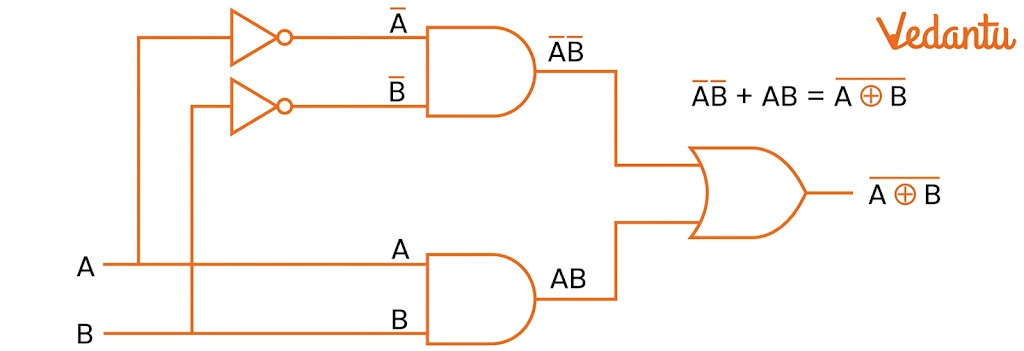
XNOR Gate Using Basic Logic Gates
One common xnor gate circuit diagram uses the basic gates:
AND
OR
NOT
The required Boolean expression is:
Y = AB + A'B'
To implement this:
use two NOT gates to get A' and B'
use one AND gate to get AB
use another AND gate to get A'B'
combine both outputs using an OR gate
This gives the final XNOR output.
This method is conceptually simple and clearly shows how the XNOR gate equation is translated into hardware.
XNOR Gate Using NAND Gate
The XNOR gate can also be formed using NAND gates only. This is important because NAND is a universal gate, meaning any logic function can be built using NAND gates alone.
According to the file, we require five two-input NAND gates to construct an XNOR gate. The intermediate outputs first generate XOR behavior, and then that XOR output is inverted again using another NAND arrangement to obtain XNOR.
Important points:
total 5 NAND gates are needed
the circuit first behaves like XOR
final inversion gives XNOR
This type of construction is common in digital design exercises.
XNOR Gate Using NOR Gate
An XNOR gate can also be implemented using NOR gates only, and again five NOR gates are required. NOR is also a universal gate, so it can be used to build any logical function.
The process involves:
generating intermediate inverted terms
combining them through NOR logic
simplifying using De Morgan’s law
This method is useful in exam questions that ask students to implement gates using only NOR.
XNOR Gate Using Transistors
The file also describes the implementation of XNOR gate using transistors. It states that an efficient XNOR design can be made using five transistors, and this is preferred over less efficient designs using larger transistor counts.
In this arrangement:
the initial transistor pair functions like a NAND gate
a middle transistor acts as a switch
the final transistors help produce OR-like behavior
Together, these parts create XNOR functionality. This is an important point for students learning transistor-level logic implementation.
XNOR Gate IC Number
The query xnor gate IC number is very common in electronics searches. In practice, XNOR functionality is commonly associated with standard IC families that implement exclusive-NOR logic. When discussing the xnor gate IC number, students usually refer to integrated circuits designed to perform XNOR operations directly or through equivalently labelled logic packages.
For board-style and concept learning, the most important point is not only memorising the IC number, but understanding:
the logic operation
the truth table
the symbol
the Boolean expression
the circuit construction
That said, in practical electronics, XNOR gate IC packages are available in standard digital logic families.
Applications of XNOR Gate
The XNOR gate has many practical applications because it checks input equality.
1. Comparators
XNOR gates are used in comparators to compare binary values bit by bit. If all corresponding bits match, the output remains HIGH.
2. Binary Arithmetic
They help detect equal values in binary addition and subtraction circuits.
3. Parity Checking
XNOR gates are used in parity checking systems where equality of bit patterns is important.
4. Multiplexers
They assist in selecting channels or validating signal matching conditions in multiplexer circuits.
5. Latch and Flip-Flop Control
XNOR gates can enable or disable storage elements depending on input matching.
6. Decoders
They help activate outputs based on matching input code patterns.
7. Clock Synchronization
XNOR gates are used in synchronization circuits for comparing clock signals.
8. Data Storage
When combined with memory circuits such as SRAM structures, XNOR gates can improve reliability.
9. Control Logic
They are useful in digital control and sequencing operations.
10. Full Adders and ALUs
XNOR gates are important in arithmetic logic units and digital arithmetic design.
Advantages of XNOR Gate
The file lists several advantages of XNOR gate:
1. Simplicity
It is simple to understand and implement.
2. Dedicated Equality Testing
It is purpose-built for comparison or equality checking.
3. Complementary Outputs
It provides complementary logic behavior relative to XOR.
4. Ease of Integration
It simplifies the design of circuits that involve comparisons.
5. Data Reliability
Its use in memory and control systems improves data integrity and reliability.
Disadvantages of XNOR Gate
The file also notes some disadvantages of XNOR gate:
1. Limited Functionality
It is mainly useful for equality comparison and not for a wide range of logic operations.
2. Design Complexity in Large Circuits
Designing bigger circuits using only XNOR gates can be inefficient and difficult.
3. Input Dependency
It is more naturally suited to even-numbered equality comparisons and can be less flexible in some logic arrangements.
4. Unsuitable for Many Arithmetic Tasks
Compared with gates like AND and XOR, XNOR is not the first choice for many core arithmetic operations.
FAQs on XNOR Gate: Truth Table, Symbol, Boolean Expression, Formula and Circuit Diagram
1. What is a XNOR logic gate?
A XNOR logic gate is a digital gate that gives output 1 only when both inputs are the same, either 0 and 0 or 1 and 1. It is mainly used to check equality between two inputs.
2. What is XOR and XNOR gate?
An XOR gate gives output 1 when the inputs are different.
An XNOR gate gives output 1 when the inputs are the same.
So, XOR checks difference, while XNOR checks similarity.
3. Is XNOR logically complete?
No, XNOR is not logically complete. It cannot alone form all other logic gates as easily as universal gates like NAND and NOR.
4. Is XNOR equal to not XOR?
Yes, XNOR is the inverse of XOR.
In simple words:
XNOR = NOT (XOR)
5. How to solve XNOR gate?
To solve an XNOR gate, compare the two inputs:
If both inputs are the same → output is 1
If the inputs are different → output is 0
So:
0, 0 → 1
0, 1 → 0
1, 0 → 0
1, 1 → 1
6. What are the 7 types of gates?
The seven basic logic gates are:
AND
OR
NOT
NAND
NOR
XOR
XNOR
7. Why is XNOR gate called exclusive?
It is called exclusive NOR because it is the opposite of the XOR gate. It gives a true output only when the two inputs are exactly equal.
8. Is XNOR even OR odd?
XNOR acts as an even detector. It gives output 1 when there is an even number of 1s in the input combination.