


Physics Notes for Chapter 3 Current Electricity Class 12 - FREE PDF Download


3.1 Introduction
1. In earlier chapters, charges were considered at rest; in this chapter, we focus on charges in motion, which constitute an electric current.
2. Electric current occurs naturally in phenomena like lightning, where charges flow from clouds to the earth.
3. Steady currents are found in everyday devices like torches and clocks.
4. This chapter covers the basic laws governing steady electric currents in conductors.
5. Steady electric current is similar to the smooth flow of water in a river, unlike the erratic flow of lightning.
6. Understanding steady electric current is essential for comprehending the functioning of various electrical devices.
3.2 Electric Current
1. Electric current (I) is defined as the rate at which charge flows through a cross-sectional area.
2. For steady current, $I = \frac{q}{t} $, where $ q $ is the net charge and $ t $ is the time interval.
3. Current can flow in both directions and if the current is negative, it indicates a flow in the opposite direction.
4. For non-steady currents, the instantaneous current is defined as $I = \lim_{\Delta t \to 0} \frac{\Delta Q}{\Delta t} $, where $ \Delta Q $ is the charge flowing in time $ \Delta t $.
5. The SI unit of electric current is the ampere (A).
6. Currents in household devices are typically of the order of a few amperes, while lightning carries tens of thousands of amperes.
3.3 Electric Currents in Conductors
1. Charges experience a force when an electric field is applied, leading to motion and the creation of an electric current.
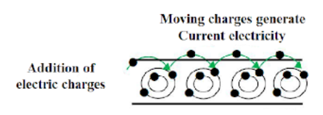
2. In some materials, like metals, electrons are free to move and contribute to electric current.
3. Conductors, such as metals, allow current to flow because of free electrons that move in the presence of an electric field.
4. When no electric field is applied, the thermal motion of electrons causes random movement, with no net current.
5. When an electric field is applied, electrons move in a directed manner, creating a net electric current.
6. Devices like batteries and cells provide a steady supply of charges, resulting in continuous current.
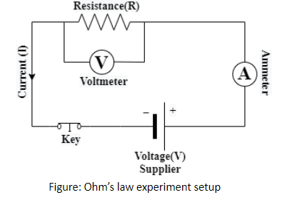
3.4 Ohm’s Law
1. Ohm's Law: The law states that the potential difference $ V $ across a conductor is directly proportional to the current $ I $ flowing through it, expressed as $ V = IR $, where $ R $ is the resistance of the conductor.
2. Resistance (R): Resistance is the constant of proportionality in Ohm's Law and depends on both the material and dimensions of the conductor.
3. Factors Affecting Resistance: Resistance $ R $ is proportional to the length $ l $ of the conductor and inversely proportional to the cross-sectional area $ A $. $ R = \frac{\rho l}{A} $, where $ \rho $ is the resistivity of the material.
4. Resistivity ($ \rho $): It is a material-specific property that influences the resistance of the conductor. Metals generally have low resistivity, while insulators have high resistivity.
5. Current Density (j): It is defined as the current per unit area, $ j = \frac{I}{A} $, and is proportional to the applied electric field.
6. Conductivity (o): The reciprocal of resistivity, conductivity $ \sigma $, relates to how easily current flows through a material, given by $ j = \sigma E $.
3.5 Drift of Electrons and the Origin of Resistivity
1. Electron Drift: When an electric field is applied, electrons accelerate and move in the opposite direction to the field. However, due to collisions with ions, they attain an average constant velocity known as drift velocity.
2. Drift Velocity (vd): The average velocity attained by electrons due to the electric field is given by $ v_d = \frac{eE\tau}{m} $, where $ e $ is the charge of the electron, $ E $ is the electric field, $ \tau $ is the relaxation time, and $ m $ is the electron mass.
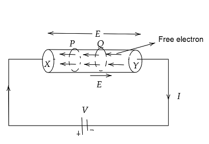
3. Relation to Current: The current in a conductor depends on the number of electrons per unit volume ($ n $), the drift velocity ($ v_d $), and the cross-sectional area ($ A $) of the conductor. $ I = n e A v_d $.
4. Conductivity ($ \sigma $): The conductivity of a material is determined by the electron density $ n $, relaxation time $ \tau $, and mass $ m $, given by $ \sigma = \frac{n e^2 \tau}{m} $.
5. Ohm’s Law from Drift: The drift velocity causes a steady flow of electrons, and this results in a current. Ohm’s Law can be derived from the relationship between current density and electric field.
6. Resistivity and Temperature: Resistivity of a material can change with temperature, as the relaxation time $ \tau $ is affected by temperature variations, leading to changes in resistance.
3.5.1 Mobility
1. Definition of Mobility: Mobility $ \mu $ is defined as the magnitude of the drift velocity per unit electric field, given by $ \mu = \frac{|v_d|}{E} $.
2. SI Unit: The SI unit of mobility is $ m^2/Vs $. In practical terms, it is often measured in $ cm^2/Vs $.
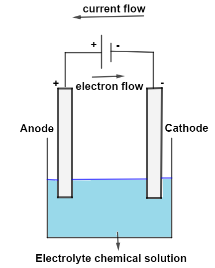
3. Mobility of Charge Carriers: In different mediums, mobile charge carriers vary:
In metals: Electrons
In ionized gases: Electrons and positive ions
In electrolytes: Both positive and negative ions
4. Formula for Mobility: From the drift velocity equation $ v_d = \frac{eE\tau}{m} $, the mobility is given by $ \mu = \frac{e\tau}{m} $, where $ \tau $ is the average time between collisions, $ e $ is the charge of an electron, and $ m $ is the mass of the electron.
5. Relation with Conductivity: Higher mobility implies greater conductivity, as charge carriers can move more freely in response to an electric field.
6. Positive Mobility: Mobility is always positive and indicates how efficiently charges move under the influence of an electric field.
3.6 Limitations of Ohm’s Law
1. Non-linear Materials: Ohm’s law is valid for materials where the current $ I $ is directly proportional to the voltage $ V $. However, in some materials, $ V $ is not proportional to $ I $, leading to deviations from Ohm's law (e.g., semiconductors).
2. Directional Dependency: In some devices like diodes, the current changes when the direction of the voltage is reversed, violating the linearity of Ohm's law.
3. Non-unique $ V $-$ I $ Relationship: Certain materials, such as GaAs (Gallium Arsenide), can have multiple voltage values for the same current, which contradicts the linear relationship expected from Ohm’s law.
4. Widely Used Non-Ohmic Devices: Despite these limitations, materials and devices that do not follow Ohm’s law are commonly used in electronic circuits.
5. Applications of Non-Ohmic Behavior: Examples of non-Ohmic materials include diodes and semiconductors, which are integral to modern electronic devices.
6. Scope of Study: In this chapter and subsequent ones, we focus on materials that obey Ohm’s law to simplify the study of electric currents.
3.7 Resistivity of Various Materials
1. Classification by Resistivity: Materials are classified into conductors, semiconductors, and insulators based on their resistivities.
Conductors: Metals like copper and silver, with low resistivities ranging from $ 10^{-8} \ \Omega \cdot m $ to $ 10^{-6} \ \Omega \cdot m $.
Insulators: Materials like rubber and ceramics, with extremely high resistivities, up to 18 orders of magnitude higher than metals.
Semiconductors: Materials like silicon, with intermediate resistivities that decrease with temperature.
2. Temperature Effect: For semiconductors, resistivity decreases with an increase in temperature, making them useful for electronic applications.
3. Use of Impurities: The resistivity of semiconductors can be altered by adding impurities, a process called doping, used in devices like transistors.
4. Conductive Metals: Metals have free electrons that allow easy flow of current, making them good conductors with low resistivity.
5. Insulators: In contrast, insulators have tightly bound electrons, preventing the flow of current and resulting in high resistivity.
6. Applications: Conductors are used in wiring, semiconductors in electronic devices, and insulators in electrical safety.
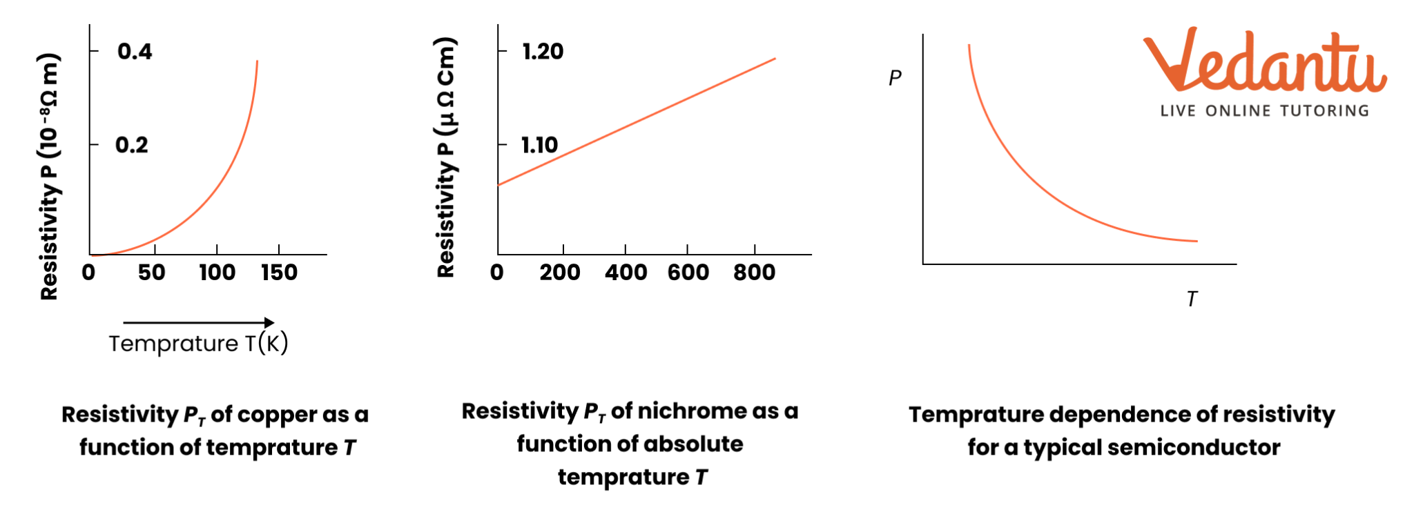
3.8 Temperature Dependence of Resistivity
1. Resistivity and Temperature: The resistivity of materials changes with temperature, expressed by $ \rho_T = \rho_0 [1 + \alpha (T - T_0)] $, where $ \alpha $ is the temperature coefficient of resistivity.
2. Positive Coefficient for Metals: In metals, resistivity increases with temperature due to more frequent collisions of electrons as thermal motion increases.
3. Nichrome and Constantan: Some materials, like Nichrome and Manganin, show weak dependence of resistivity on temperature, making them useful in precision resistors.
4. Semiconductors: Unlike metals, semiconductors exhibit a decrease in resistivity with an increase in temperature due to the increase in charge carriers.
5. Deviations at Low Temperatures: At very low temperatures, metals exhibit non-linear behaviour, and the relationship between resistivity and temperature deviates from the linear model.
6. Practical Use: Understanding the temperature dependence of resistivity is important in designing devices that operate under varying temperature conditions, such as thermistors and temperature sensors.
3.9 Electrical Energy and Power
1. Energy Dissipation in a Conductor: When a current $ I $ flows through a conductor with a potential difference $ V $ between its ends, electrical energy is converted into heat energy due to the collisions of charge carriers with atoms.
2. Energy Lost as Heat: The energy lost as heat in time $ \Delta t $ is given by $ \Delta W = IV\Delta t $. This is due to the transformation of the potential energy of the charges into thermal energy.
3. Power Dissipated: The power dissipated in a conductor is given by $ P = IV $. Using Ohm's law ($ V = IR $), the power can also be expressed as $ P = I^2R $ or $ P = \frac{V^2}{R} $.
4. Ohmic Loss: The heat generated in the resistor due to the current flow is known as ohmic loss. This is the basis of the heating effect seen in electrical appliances like electric bulbs and heaters.
5. Power Transmission: To minimize power loss in transmission cables, electricity is transmitted at high voltages, as power loss in cables is inversely proportional to the square of the voltage ($ P_c = \frac{P^2 R_c}{V^2} $).
6. Role of Transformers: High-voltage transmission is dangerous for use in households, so transformers are used to step down the voltage to a safe level before distributing it for use.
3.10 Cells, EMF, and Internal Resistance
1. Electromotive Force (EMF): The EMF ($ \epsilon $) of a cell is the potential difference between its positive and negative terminals when no current is flowing through the circuit. It represents the ability of the cell to do electrical work.
2. Internal Resistance (r): All cells have some internal resistance, which opposes the flow of current within the cell. The terminal voltage $ V $ of the cell when current $ I $ flows is given by $ V = \epsilon - Ir $.
3. Energy Source: The chemical energy of a cell is converted into electrical energy. When current flows through the circuit, some energy is lost due to internal resistance, leading to a drop in terminal voltage.
4. Maximum Current: The maximum current that a cell can provide is $ I_{\text{max}} = \frac{\epsilon}{r} $, but in practice, drawing too much current can damage the cell.
5. External Circuit: The total voltage across a resistor $ R $ connected to the cell is $ V = IR $, where $ V $ is the terminal voltage, and $ I $ is the current through the circuit.
6. Practical Implications: For practical purposes, the internal resistance of cells can be neglected when $ \epsilon \gg Ir $.
3.11 Cells in Series and Parallel
1. Series Combination: When cells are connected in series, their EMFs add up. The total EMF of the combination is $ \epsilon_{\text{eq}} = \epsilon_1 + \epsilon_2 + ... $. The total internal resistance is the sum of individual internal resistances: $ r_{\text{eq}} = r_1 + r_2 + ... $.
2. Parallel Combination: In parallel, the total EMF is given by $ \epsilon_{\text{eq}} = \frac{\epsilon_1 r_2 + \epsilon_2 r_1}{r_1 + r_2} $. The total internal resistance is given by $ \frac{1}{r_{\text{eq}}} = \frac{1}{r_1} + \frac{1}{r_2} + ... $.
3. Series-Parallel Applications: Series combinations provide higher voltage, while parallel combinations provide lower internal resistance, optimizing battery performance for various applications.
4. Voltage Reversal: If cells with opposing EMFs are connected in series, the total EMF is the difference between the two EMFs ($ \epsilon_{\text{eq}} = \epsilon_1 - \epsilon_2 $ if $ \epsilon_1 > \epsilon_2 $).
5. Applications: Series combinations are used where high voltage is needed, while parallel combinations are used to provide a stable current with lower internal resistance.
3.13 Wheatstone Bridge
1. Definition: The Wheatstone bridge is an electrical circuit used to measure unknown resistance by balancing two legs of a bridge circuit. It consists of four resistors $ R_1, R_2, R_3, $ and $ R_4 $, a power source, and a galvanometer.
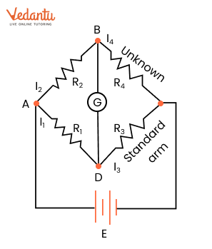
2. Components:
Battery Arm (AC): The source of voltage is connected across the diagonally opposite points A and C.
Galvanometer Arm (BD): A galvanometer is connected between points B and D to detect any current flowing through the bridge.
3. Balanced Bridge Condition:
A special case of the Wheatstone bridge occurs when the current through the galvanometer is zero, i.e., $ I_g = 0 $.
In this balanced condition, the current through the resistors in arms ADB and CBD is equal: $ I_1 = I_3 $ and $ I_2 = I_4 $.
4. Kirchhoff's Loop Rule:
For the loop ADBA: $-I_1 R_1 + I_2 R_2 = 0$
For the loop CBDC: $I_2 R_4 - I_1 R_3 = 0$
5. Balance Condition:
From the equations derived using Kirchhoff’s rules, the balance condition of the Wheatstone bridge is:
\[\frac{R_1}{R_2} = \frac{R_3}{R_4}\]
This condition ensures that there is no current through the galvanometer, indicating a balanced bridge.
6. Practical Application:
The Wheatstone bridge is commonly used to determine unknown resistance. When the bridge is balanced, the unknown resistance $ R_4 $ can be calculated using the formula:
\[R_4 = \frac{R_2 \times R_3}{R_1}\]
7. Meter Bridge:
A practical device that uses the Wheatstone bridge principle is the meter bridge, which allows precise measurement of unknown resistances by adjusting a known resistor to achieve a balanced condition.
Current Electricity Class 12 Notes Physics - Basic Subjective Questions
Section-A (1 Mark Questions)
1. What is the direction of the flow of current through an electric circuit?
Ans. From high potential to low potential
2. A meter bridge is balanced with known resistance in the right gap and a metal wire in the left gap. If the metal wire is heated the balance point will shift to which side?
Ans. $\dfrac{V_{1}}{V_{2}}=\dfrac{l_{1}}{l_{2}}$
The resistance of the metal increases on heating
$\Rightarrow l_{2}^{'}> l_{1}$
∴ The balance point shifts towards the right.
3. The potential difference across the terminals of a battery is 10V when there is a current of 3A in the battery from the negative to the positive terminal. When the current is 2A in the reverse direction, the potential difference becomes 15 V. Find the internal resistance of the battery.
Ans. E-3r=10 …(i)
E+3r=10 …(ii)
Solving these two equations we get $r=1\Omega$
4. A wire of resistivity ρ is stretched to double its length. What will be its new resistivity?
Ans. The resistivity remains the same as it does not depend upon the length of the wire.
5. What will happen to the relaxation time of electrons in a metal, if the temperature is changed?
Ans. The relaxation time of electrons decreases with the rise in temperature of the metal.
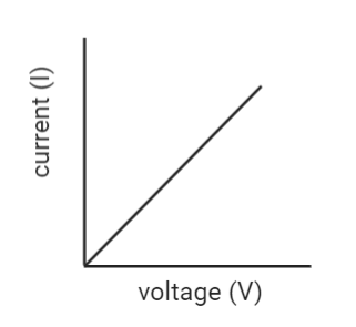
6. Which physical quantity does the slope of the voltage versus current graph for a metallic conductor represent? Give its SI unit.
Ans. The slope of the voltage versus current graph for a metallic conductor represents resistance. It is measured in ohm.
7. Define the drift velocity of electrons.
Ans. The mean velocity acquired by electrons in a conductor when an external electric field is applied to it is called the drift velocity of electrons.
8. A resistance R is connected across a cell of emf ε and internal resistance r. A potentiometer now measures the potential difference between the terminals, of the cell as V. Write the expression for ‘r’ in terms of ε, V and R.
Ans. The required relation is $r=\left ( \dfrac{\varepsilon }{v}-1 \right )R$
9. A carbon resistor is marked in red, yellow, and orange bands. What is the approximate resistance of the resistor?
Ans. $24\times 10^{3}\Omega \pm20%$
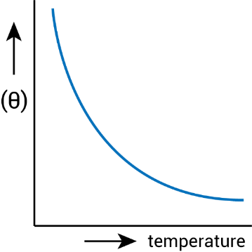
10. Draw the graph showing the variation of conductivity with temperature for a metallic conductor.
Ans.
Section-B (2 Marks Questions)
11. If the potential difference V applied across a conductor is increased to 2V, how will the drift velocity of the electron change?
Ans. $V_{d}=\dfrac{eE\tau }{m}$
$V_{d}=\dfrac{eV\tau }{lm}$
∴ Double the P.D. means drift velocity gets doubled.
12. Resistivities of copper, silver and manganin are $1\cdot 7\times 10^{-8}m$ , $1\cdot 0\times 10^{-8}m$ and $44\times 10^{-8}m$ . Respectively which of these is the best conductor?
Ans. For a particular length and area of cross-section, the resistance is directly proportionate to, specific resistance. Therefore, silver is the best conductor because its specific resistance is less.
13. Name any one material having a small value of temperature coefficient of resistance. Write one use of this material.
Ans. Nichrome, an alloy has a small value of temperature coefficient of resistance. It is used for making standard resistance coils.
14. Two wires A and B are of the same metal and of the same length and have their areas of cross-section in the ratio 2:1 if the same potential difference is applied across each wire in turn, what will be the ratio of current flowing in A & B?
Ans. Since $R=\dfrac{1}{A}$
If the area is in the ratio 2: 1 resistance will be in the ratio 1: 2.
And $I=\dfrac{V}{R}\Rightarrow I=\dfrac{1}{R}$
∴ Current will be in the ratio 2: 1
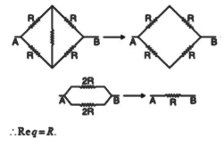
15. Calculate the equivalent resistance between points A and B in the figure given below.
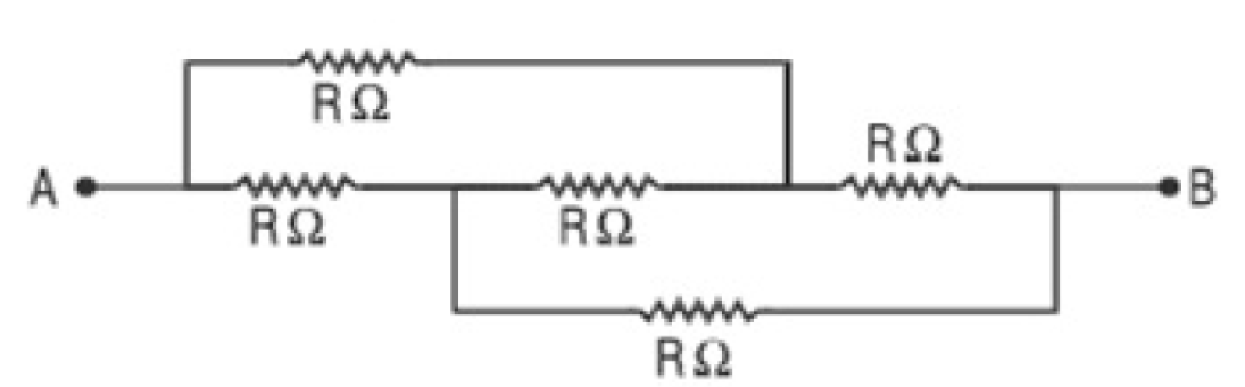
Ans.
16. Under what conditions is heat produced in an electric circuit:
(i) directly proportional
(ii) inversely proportional to the resistance of the circuit
Ans.
(i) If 1 in the circuit is constant because $H=l^{2}Rt$
(ii) If V in circuit is constant because $H=\dfrac{V^{2}}{R}t$
Important Formulas of Class 12 Chapter 3 Physics You Shouldn’t Miss!
Here are the essential formulas for Class 12 Physics Chapter 3, Current Electricity, that you should know:
1. Ohm’s Law
Formula: $ V = I \times R $
Where:
$ V $ = Potential Difference (Volts)
$ I $ = Current (Amperes)
$ R $ = Resistance (Ohms)
Description: States that the current through a conductor between two points is directly proportional to the voltage across the two points.
2. Electrical Power
Formulas:
$ P = V \times I $
$ P = I^2 \times R $
$ P = \frac{V^2}{R} $
Where:
$ P $ = Power (Watts)
$ V $ = Potential Difference (Volts)
$ I $ = Current (Amperes)
$ R $ = Resistance (Ohms)
Description: Power represents the rate at which electrical energy is consumed or generated.
3. Resistance
Formula: $ R = \rho \times \frac{L}{A} $
Where:
$ R $ = Resistance (Ohms)
$ \rho $ = Resistivity of the material (Ohm-meter)
$ L $ = Length of the conductor (meters)
$ A $ = Cross-sectional Area (square meters)
Description: Determines how much a material opposes the flow of electric current.
4. Resistivity and Temperature Dependence
Formula: $ R = R_0 [1 + \alpha (T - T_0)] $
Where:
$ R $ = Resistance at temperature $ T $
$ R_0 $ = Resistance at reference temperature $ T_0 $
$ \alpha $ = Temperature coefficient of resistance
$ T $ = Temperature (°C or K)
$ T_0 $ = Reference temperature (°C or K)
Description: Shows how resistance changes with temperature.
5. Kirchhoff’s Laws
a. Kirchhoff’s Current Law (Junction Rule)
Formula: $ \sum I_{in} = \sum I_{out} $
Description: The total current entering a junction equals the total current leaving the junction.
b. Kirchhoff’s Voltage Law (Loop Rule)
Formula: $ \sum V = 0 $
Description: The sum of all potential differences around any closed loop in a circuit is zero.
6. Combination of Resistances
a. Series Combination
Formula: $ R_{\text{total}} = R_1 + R_2 + R_3 + \dots $
Description: Total resistance is the sum of individual resistances.
b. Parallel Combination
Formula: $ \frac{1}{R_{\text{total}}} = \frac{1}{R_1} + \frac{1}{R_2} + \frac{1}{R_3} + \dots $
Description: Total resistance is found by taking the reciprocal of the sum of reciprocals of individual resistances.
7. Energy Consumed
Formula: $ E = V \times I \times t $
Where:
$ E $ = Energy (Joules)
$ V $ = Potential Difference (Volts)
$ I $ = Current (Amperes)
$ t $ = Time (seconds)
Description: Calculates the electrical energy consumed over a period.
8. Electromotive Force (EMF) and Internal Resistance
Formula: $ \mathcal{E} = V + I \times r $
Where:
$ \mathcal{E} $ = Electromotive Force (Volts)
$ V $ = Terminal Voltage (Volts)
$ I $ = Current (Amperes)
$ r $ = Internal Resistance (Ohms)
Description: Relates the EMF of a cell to its terminal voltage and internal resistance.
9. Drift Velocity
Formula: $ v_d = \frac{I}{n \times A \times e} $
Where:
$ v_d $ = Drift Velocity (meters/second)
$ I $ = Current (Amperes)
$ n $ = Charge Carrier Density (per cubic meter)
$ A $ = Cross-sectional Area (square meters)
$ e $ = Elementary Charge (Coulombs)
Description: Represents the average velocity of charge carriers in a conductor.
Importance of Chapter 3 Current Electricity Class 12 Notes
Key Concepts Simplified: The notes break down important concepts such as Ohm’s Law, Kirchhoff’s Laws, resistance, and electric circuits, making it easier for students to understand and apply them in problems.
Important Formulae at a Glance: The notes compile all the important formulae in one place, ensuring that students can quickly revise them before exams.
Step-by-Step Problem Solving: Class 12 Physics notes provide a detailed approach to solving numerical problems, making complex calculations easier to grasp.
Improves Exam Preparation: These notes are structured to cover the most frequently asked questions, ensuring students are well-prepared for their board exams and competitive tests.
Time-Efficient Revision: With well-organized notes, students can save time during last-minute revisions, focusing on key concepts and formulae.
Tips for Learning the Class 12 Physics Chapter 3 Current Electricity
Understand the Concepts: Don’t just memorise the formulas. Make sure you understand the underlying physics concepts to apply them effectively.
Practice Problems: Apply these formulas to various problems to strengthen your problem-solving skills.
Dimensional Analysis: Always check the units to ensure that your calculations are consistent.
Circuit Diagrams: Familiarise yourself with different types of circuit diagrams as they are essential for applying Kirchhoff’s Laws and combination formulas.
Revision: Regularly revise these formulas and their applications to retain them in your memory.
Conclusion
Understanding Chapter 3: Current Electricity is essential for a solid understanding of electrostatics in Class 12 Physics. By grasping the fundamental concepts of electric potential, potential energy, and capacitance, students can better understand the behaviour of electric fields and the practical applications of capacitors in various electronic devices. The chapter not only provides critical knowledge for solving complex physics problems but also offers insights into real-world applications and technologies. Through proper study, practice, and application of the key formulas and concepts, students will be well-prepared for both their exams and future studies in physics and engineering.
Related Study Materials for Class 12 Physics Chapter 3 Current Electricity
Students can also download additional study materials provided by Vedantu for Class 12 Physics Chapter 3 Current Electricity.
Chapter-wise Links for Class 12 Physics Notes PDF FREE Download
Related Study Materials Links for Class 12 Physics
Along with this, students can also download additional study materials provided by Vedantu for Physics Class 12–


FAQs on CBSE Notes Class 12 Physics Chapter 3 - Current Electricity - 2026-27
1. What are the key concepts students should revise first from Class 12 Physics Chapter 3 Current Electricity?
Begin your revision with Ohm’s Law, Kirchhoff’s Rules, the definitions of resistance and resistivity, and the behaviour of series and parallel circuits. Next, focus on the effects of temperature on resistance, drift velocity, mobility, and electrical power formulas. Ensure you can explain each concept clearly for good exam performance.
2. How can a concept map help when revising Current Electricity in Class 12 Physics?
A concept map allows you to visually connect formulas, definitions, and laws. For Current Electricity, map out the links between electric current, Ohm’s Law, circuit rules, and types of materials, which helps in quick recall and understanding how each topic interrelates during your final revision.
3. What summary points should you focus on for exam-oriented revision of current electricity?
When revising, summarize:
- The meaning of electric current (charge flow per time)
- Ohm's Law and the factors affecting resistance
- Drift velocity and its connection with current
- Series and parallel circuit behaviour
- Temperature dependence of resistivity for metals and semiconductors
- The concept of electromotive force (EMF) and internal resistance
4. How should students approach formula revision for Class 12 Current Electricity?
List all key formulas such as V = IR, P = VI, R = \(\rho \frac{L}{A}\), and resistivity-temperature relationships. Write these formulas with units and variable meanings. Practicing problems involving each ensures you remember when and how to apply them, which is crucial for board exams.
5. What is the best revision strategy for complex concepts like Kirchhoff’s Laws or the Wheatstone Bridge?
Start with the statement and mathematical expression of each law. Practice drawing and labelling circuit diagrams. Summarize steps to solve numerical problems using these laws, and solve representative questions to reinforce understanding and approach.
6. Why is understanding resistivity and its temperature dependence essential in Class 12 Current Electricity revisions?
Resistivity influences how easily current flows through materials, so its understanding is vital for comparing conductors, insulators, and semiconductors. Knowing how resistivity changes with temperature helps in explaining device performance and is commonly tested in CBSE exams.
7. How can students avoid common mistakes when revising the derivations in Current Electricity?
Review each derivation stepwise, stating all assumptions and definitions upfront. Use proper units throughout, and relate the derived result back to physical meaning. Practicing these with past exam questions helps avoid missing important steps in the answer.
8. What role does understanding the difference between drift velocity and mobility play during revision?
Drift velocity is the average velocity acquired by electrons due to an electric field, while mobility measures how quickly charge carriers move under unit field. Recognizing this difference aids in correct application of relationships and clearer explanations in both theory and numerical questions.
9. Why should students focus on the applications of Current Electricity concepts in daily life during revision?
Applying concepts like Ohm’s Law, heating effect, or power transmission to real life (e.g., electrical appliances, fuses, household wiring) boosts understanding and helps write better answers in value-based or application-based questions in CBSE exams.
10. What is the ideal order to revise the subtopics in Class 12 Physics Current Electricity for quick and effective preparation?
Begin with basics of electric current, then move to drift of electrons, Ohm’s Law and resistance, series and parallel circuits, Kirchhoff’s Laws, heating effects of current, and finish with EMF, internal resistance, and Wheatstone bridge. This order reflects logical progression and helps consolidate underlying principles efficiently.
11. How do revision notes help in mastering numerical problem-solving for Current Electricity in board exams?
Well-structured revision notes distill the problem-solving steps, highlight key equations, and provide solved examples. This enables quick referencing, troubleshooting errors, and developing speed and accuracy for marks-oriented numerical questions.
12. What common misconceptions should be clarified while reviewing Current Electricity concepts?
Clear up misconceptions such as:
- Direction of current vs. electron flow
- Resistivity and resistance being the same (they are not)
- Effect of heating on resistivity for metals vs. semiconductors
- Assuming Ohm’s Law applies to all materials (it does not)
13. What are some effective ways to revise and retain circuit analysis methods for Current Electricity?
Practice drawing clear circuit diagrams, labelling all components, and writing out the steps for solving using Kirchhoff’s Rules or equivalent resistance formulas. Reviewing example problems helps reinforce these methods and boosts retention.
14. How should students approach the revision of different types of materials based on resistivity in this chapter?
Compare properties of conductors, insulators, and semiconductors by their typical resistivity values, temperature dependence, and applications. Understanding these differences is vital for both MCQ and reasoning questions as per CBSE 2026–27 syllabus.
15. What are the most important tips for quick last-minute revision of Current Electricity before the board exam?
- Review all summaries and boxed formulas
- Go through circuit diagrams and basic laws
- Recall main definitions and units
- Practice one or two representative numericals
- Clarify the key differences between resistivity, resistance, and conductivity