Courses
Courses for Kids
Free study material
Offline Centres
More
Store Icon
Store

NCERT Solutions for Class 12 Physics Chapter 3 Current Electricity

ffImage
banner

NCERT Solutions for Class 12 Physics Chapter 3 Current Electricity - FREE PDF Download

Chapter 3 Current Electricity class 12 NCERT solutions by Vedantu, explains the principles and applications of electric current in conductors. This chapter explores the behaviour of electric charges in motion within conductors and is pivotal for understanding how electrical circuits operate, which is essential for both theoretical knowledge and practical applications in technology and engineering. This chapter also explores the properties of materials, understanding how different substances influence the flow of current through their electrical resistivity and conductivity. By practising with these Class 12 Physics NCERT Solutions, students can build confidence in their understanding and excel in their studies.

toc-symbolTable of Content
toggle-arrow


Glance on Physics Chapter 3 Class 12 - Current Electricity

  • Chapter 3 of Class 12 Physics, "Current Electricity," is an essential topic that explores the behaviour and properties of electric currents in conductors. It forms the foundation for understanding electric circuits and their applications in various technologies and devices.

  • It introduces the concept of electric current, defined as the rate of flow of electric charge. Discussions cover closed and open circuits, voltage sources (like batteries), and resistors. Understanding the flow of current in a circuit is essential.

  • In Current Electricity class 12 exercise solutions, Different arrangements of resistors in circuits are discussed, along with how they affect the total resistance and current flow.

  • Lso in current electricity class 12 solutions, Kirchhoff's laws are introduced to analyse more complex circuits. Formulas to calculate electrical energy (E) and power (P) are discussed. Various arrangements of cells in a circuit are discussed, such as series and parallel combinations, and their effects on the voltage and current.

  • This article contains chapter notes, important questions, exemplar solutions, exercises, and video links for Chapter 3 - Current Electricity, which you can download as PDFs.

  • There are 9 fully solved questions in class 12th physics chapter 3 Current Electricity.

Competitive Exams after 12th Science
tp-imag
bottom-arrow
tp-imag
bottom-arrow
tp-imag
bottom-arrow
tp-imag
bottom-arrow
tp-imag
bottom-arrow
tp-imag
bottom-arrow
More Free Study Material for Current Electricity
icons
Revision notes
823.2k views 12k downloads
icons
Important questions
797.1k views 12k downloads
icons
Ncert books
809.1k views 15k downloads

Access NCERT Solutions for Class 12 Physics Chapter 3 – Current Electricity

1. The storage battery of a car has an emf of 12 V. If the internal resistance of the battery is \[0.4\Omega \] , what is the maximum current that can be drawn from the battery?

Ans: In the above question it is given that:

Emf of the battery, $E=12V$

Internal resistance of the battery, $r=0.4\Omega $

Consider the maximum current drawn from the battery to be $I$.

Therefore, using Ohm’s law,

$E=Ir$

$\Rightarrow I=\frac{E}{r}$

$\Rightarrow I=\frac{12}{0.4}$

$\Rightarrow I=30A$

Clearly, the maximum current drawn from the given battery is $30A$ .


2. A battery of emf 10 V and internal resistance $3\Omega $ is connected to a resistor. If the current in the circuit is 0.5 A, what is the resistance of the resistor? What is the terminal voltage of the battery when the circuit is closed?

Ans: In the above question it is given that:

Emf of the battery, E = 10 V

Internal resistance of the battery, $r=3\Omega $

Current in the circuit, $I=0.5A$ 

Consider the resistance of the resistor to be $R$.

Therefore, using Ohm’s law,

$I=\frac{E}{R+r}$

$R+r=\frac{E}{I}$

$\Rightarrow R+r=\frac{10}{0.5}$

$\Rightarrow R+r=20$

$\Rightarrow R=20-3=17\Omega $

Let the terminal voltage of the resistor be $V$.

Using the Ohm’s law,

$V=IR$

$\Rightarrow V=0.5\times 17=8.5V$

Thus, the resistance of the resistor is $17\Omega $ and the terminal voltage is $8.5V$ .


3. At room temperature ${{27.0}^{\circ }}C$, the resistance of a heating element is $100\Omega $. What is the temperature of the element if the resistance is found to be $117\Omega $, given that the temperature coefficient of the material of the resistor is $1.70\times {{10}^{-4}}^{\circ }{{C}^{-1}}$ ?

Ans: In the above question it is given that at room temperature $(T={{27.0}^{\circ }}C)$, the resistance of the heating element is $100\Omega $ (say R).

Also, the heating element’s temperature coefficient is given to be $\alpha =1.70\times {{10}^{-4}}{}^\circ {{C}^{-1}}$.

Now, it is said that the resistance of the heating element at an increased temperature (say ${{T}_{1}}$) is $117\Omega $ (say ${{R}_{1}}$). To compute this unknown increased temperature ${{T}_{1}}$, the formula for temperature coefficient of a material can be used. It is known that temperature co-efficient of a material provides information on the nature of that material with respect to its change in resistance with temperature. Mathematically,

$\alpha =\frac{{{R}_{1}}-R}{R\left( {{T}_{1}}-T \right)}$

$\Rightarrow {{T}_{1}}-T=\frac{{{R}_{1}}-R}{R\alpha }$

Substituting the given values,

$\Rightarrow {{T}_{1}}-27=\frac{117-100}{100\times 1.70\times {{10}^{-4}}}$

$\Rightarrow {{T}_{1}}-27=1000$

$\Rightarrow {{T}_{1}}={{1027}^{\circ }}C$

Clearly, it is at ${{1027}^{\circ }}C$ when the resistance of the element is $117\Omega $.


4. A negligibly small current is passed through a wire of length 15 m and uniform cross-section $6.0\times {{10}^{-7}}{{m}^{2}}$ , and its resistance is measured to be $5.0\Omega $ . What is the resistivity of the material at the temperature of the experiment?

Ans: In the above question it is given that:

Length of the wire, $l=15m$

Area of cross-section of the wire, $a=6.0\times {{10}^{-7}}{{m}^{2}}$

Resistance of the material of the wire, $R=5.0\Omega $

Let resistivity of the material of the wire be $\rho $

It is known that, resistance is related with the resistivity as:

$R=\rho \frac{l}{A}$

$\Rightarrow \rho =\frac{RA}{l}$

$\Rightarrow \rho =\frac{5\times 6.0\times {{10}^{-7}}}{15}$

$\Rightarrow \rho =2\times {{10}^{-7}}{{m}^{2}}$

Therefore, the resistivity of the material is $2\times {{10}^{-7}}{{m}^{2}}$ .


5. A silver wire has a resistance of \[2.1\Omega \] at ${{27.5}^{\circ }}C$ , and a resistance of $2.7\Omega $ at ${{100}^{\circ }}C$. Determine the temperature coefficient of resistivity of silver.

Ans: In the above question it is given that:

Temperature, ${{T}_{1}}={{27.5}^{\circ }}C$.

Resistance of the silver wire at ${{T}_{1}}$ is ${{R}_{1}}=2.1\Omega $ .

Temperature, ${{T}_{2}}={{100}^{\circ }}C$ .

Resistance of the silver wire at ${{T}_{2}}$ is ${{R}_{2}}=2.7\Omega $ .

Let the temperature coefficient of silver be $\alpha $ . It is known that temperature co-efficient of a material provides information on the nature of that material with respect to its change in resistance with temperature. Mathematically, it is related with temperature and resistance by the formula:

$\alpha =\frac{{{R}_{2}}-{{R}_{1}}}{{{R}_{1}}\left( {{T}_{2}}-{{T}_{1}} \right)}$

$\Rightarrow \alpha =\frac{2.7-2.1}{2.1\left( 100-27.5 \right)}={{0.0039}^{\circ }}{{C}^{-1}}$

Clearly, the temperature coefficient of silver is ${{0.0039}^{\circ }}{{C}^{-1}}$.


6. A heating element using nichrome connected to a 230 V supply draws an initial current of 3.2A which settles after a few seconds to a steady value of 2.8 A. What is the steady temperature of the heating element if the room temperature is ${{27}^{\circ }}C$ ? Temperature coefficient of resistance of nichrome averaged over the temperature range involved is $1.70\times {{10}^{-4}}^{\circ }{{C}^{-1}}$ .

Ans: In the above question it is given that:

Supply voltage is $V=230V$

Initial current drawn is ${{I}_{1}}=3.2A$.

Let the initial resistance be ${{R}_{1}}$ .

Therefore, using Ohm’s law,

${{R}_{1}}=\frac{V}{{{I}_{1}}}$

$\Rightarrow {{R}_{1}}=\frac{230}{3.2}=71.87\Omega $

Steady state value of the current is ${{I}_{2}}=2.8A$.

Let the resistance of the steady state be ${{R}_{2}}$ .

Therefore, using Ohm’s law.

${{R}_{2}}=\frac{V}{{{I}_{2}}}$

$\Rightarrow {{R}_{2}}=\frac{230}{2.8}=82.14\Omega $

Temperature co-efficient of nichrome is $\alpha =1.70\times {{10}^{-4}}^{\circ }{{C}^{-1}}$ .

Initial temperature of nichrome is ${{T}_{1}}={{27}^{\circ }}C$.

Let steady state temperature reached by nichrome be ${{T}_{2}}$ .

Now, it is known that temperature co-efficient of a material provides information on the nature of that material with respect to its change in resistance with temperature. Mathematically, it is given by

$\alpha =\frac{{{R}_{2}}-{{R}_{1}}}{{{R}_{1}}\left( {{T}_{2}}-{{T}_{1}} \right)}$

$\Rightarrow \left( {{T}_{2}}-{{T}_{1}} \right)=\frac{{{R}_{2}}-{{R}_{1}}}{{{R}_{1}}\alpha }$

Substituting the given values,

$\Rightarrow \left( {{T}_{2}}-27 \right)=\frac{82.14-71.87}{71.87\times 1.70\times {{10}^{-4}}}$

$\Rightarrow {{T}_{2}}-27=840.5$

$\Rightarrow {{T}_{2}}={{867.5}^{\circ }}C$

Clearly, the steady temperature of the heating element is ${{867.5}^{\circ }}C$.


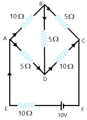
7. Determine the current in each branch of the network shown in figure:


Circuit diagram

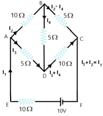
Ans: Current flowing through various branches of the circuit is represented in the given figure.


Circuit diagram to calculate the current

Consider

${{I}_{1}}=$Current flowing through the outer circuit

${{I}_{2}}=$Current flowing through branch AB

${{I}_{3}}=$Current flowing through branch AD

${{I}_{2}}-{{I}_{4}}=$Current flowing through branch BC

${{I}_{3}}+{{I}_{4}}=$Current flowing through branch CD

${{I}_{4}}=$Current flowing through branch BD

For the closed circuit ABDA, potential is zero i.e.,

$10{{I}_{2}}+5{{I}_{4}}-5{{I}_{3}}=0$

$2{{I}_{2}}+{{I}_{4}}-{{I}_{3}}=0$

${{I}_{3}}=2{{I}_{2}}+{{I}_{4}}$ …… (1)

For the closed circuit BCDB, potential is zero i.e.,

$5\left( {{I}_{2}}-{{I}_{4}} \right)-10\left( {{I}_{3}}+{{I}_{4}} \right)-5{{I}_{4}}=0$

$5{{I}_{2}}+5{{I}_{4}}-10{{I}_{3}}-10{{I}_{4}}-5{{I}_{4}}=0$

$5{{I}_{2}}-10{{I}_{3}}-20{{I}_{4}}=0$

${{I}_{2}}=2{{I}_{3}}+4{{I}_{4}}$ …… (2)

For the closed circuit ABCFEA, potential is zero i.e.,

$-10+10\left( {{I}_{1}} \right)+10\left( {{I}_{2}} \right)+5\left( {{I}_{2}}-{{I}_{4}} \right)=0$

$10=15{{I}_{2}}+10{{I}_{1}}-5{{I}_{4}}$

$3{{I}_{3}}+2{{I}_{1}}-{{I}_{4}}=2$ …… (3)

From equations (1) and (2), we obtain

${{I}_{3}}=2\left( 2{{I}_{3}}+4{{I}_{4}} \right)+{{I}_{4}}$

${{I}_{3}}=4{{I}_{3}}+8{{I}_{4}}+{{I}_{4}}$

$-3{{I}_{3}}=9{{I}_{4}}$

$-3{{I}_{4}}=+{{I}_{3}}$ …… (4)

Putting equation (4) in equation (1), we obtain

${{I}_{3}}=2{{I}_{2}}+{{I}_{4}}$

$-4{{I}_{4}}=2{{I}_{2}}$ …… (5)

It is evident from the given figure that,

${{I}_{1}}={{I}_{3}}+{{I}_{2}}$ ……. (6)

Putting equation (6) in equation (1), we obtain

$3{{I}_{2}}+2\left( {{I}_{3}}+{{I}_{2}} \right)-{{I}_{4}}=2$

$5{{I}_{2}}+2{{I}_{3}}-{{I}_{4}}=2$ …… (7)

Putting equations (4) and (5) in equation (7), we obtain

$5\left( -2{{I}_{4}} \right)+2\left( -3{{I}_{4}} \right)-{{I}_{4}}=2$

$-10{{I}_{4}}-6{{I}_{4}}-{{I}_{4}}=2$

$17{{I}_{4}}=-2$

${{I}_{4}}=-\frac{2}{17}A$

Equation (4) reduces to

${{I}_{3}}=-3\left( {{I}_{4}} \right)$

${{I}_{3}}=-3\left( -\frac{2}{17} \right)=\frac{6}{17}A$

${{I}_{2}}=-2\left( {{I}_{4}} \right)$

${{I}_{2}}=-2\left( -\frac{2}{17} \right)=\frac{4}{17}A$

${{I}_{2}}-{{I}_{4}}=\frac{4}{17}-\left( -\frac{2}{17} \right)=\frac{6}{17}$

${{I}_{3}}+{{I}_{4}}=\frac{6}{17}+\left( \frac{-2}{17} \right)=\frac{4}{17}A$

${{I}_{1}}={{I}_{3}}+{{I}_{2}}$

$\therefore {{I}_{1}}=\frac{6}{17}+\frac{4}{17}=\frac{10}{17}A$

Therefore, current in branch AB $=\frac{4}{17}A$

Current in branch BC $=\frac{6}{17}A$

Current in branch CD $=\frac{-4}{17}A$

Current in branch AD $=\frac{6}{17}A$

Current in branch BD $=\left( \frac{-2}{17} \right)A$

Total current $=\frac{4}{17}+\frac{6}{17}+\frac{-4}{17}+\frac{6}{17}+\frac{-2}{17}=\frac{10}{17}A$ .


8. A storage battery of emf 8.0 V and internal resistance $0.5\Omega $ is being charged by a 120 V DC supply using a series resistor of $15.5\Omega $. What is the terminal voltage of the battery during charging? What is the purpose of having a series resistor in the charging circuit?

Ans: In the above question it is given that:

Emf of the storage battery is $E=0.8V$.

Internal resistance of the battery is $r=0.5\Omega $ .

DC supply voltage is $V=120V$

Resistance of the resistor is $R=15.5\Omega $.

Consider effective voltage in the circuit to be $V'$, which would be the difference in the supply voltage and the emf of the battery.

$V'=V-E$

$\Rightarrow V'=120-8=112V$

Now, current flowing in the circuit is $I$ and the resistance $R$ is connected in series to the storage battery. 

Therefore, using Ohm’s law,

$I=\frac{V'}{R+r}$

$\Rightarrow I=\frac{112}{15.5+0.5}=7A$

Thus, voltage across resistor $R$would be:

$IR=7\times 15.5=108.5V$

DC supply voltage = Terminal voltage of battery + Voltage drop across $R$

Terminal voltage of battery $=120-108.5=11.5V$

A series resistor in a charging circuit takes the responsibility for controlling the current drawn from the external source. Excluding this series resistor is dangerous as the current flow would be extremely high if so.


9. The number density of free electrons in a copper conductor estimated in Example 3.1 is $8.5\times {{10}^{28}}{{m}^{-3}}$ . How long does an electron take to drift from one end of a wire 3.0 m long to its other end? The area of cross-section of the wire is $2.0\times {{10}^{-6}}{{m}^{2}}$ and it is carrying a current of 3.0 A.

Ans: In the above question it is given that:

Number density of free electrons in a copper conductor is $n=8.5\times {{10}^{28}}{{m}^{-3}}$.

Length of the copper wire is $l=3.0m$.

Area of cross-section of the wire is $A=2.0\times {{10}^{-6}}{{m}^{2}}$.

Current carried by the wire is $I=3.0A$.

Now we know that:

$I=nAe{{V}_{d}}$

Where,

$e$ is the electric charge of magnitude $1.6\times {{10}^{-19}}C$.

${{V}_{d}}$ is the drift velocity and

\[Drift\text{ }velocity=\frac{\text{Length of the wire }\left( \text{l} \right)}{\text{Time taken to cover }\left( \text{t} \right)}\]

$I=nAe\frac{l}{t}$

$\Rightarrow t=\frac{nAel}{I}$

$\Rightarrow t=\frac{3\times 8.5\times {{10}^{28}}\times 2\times {{10}^{-6}}\times 1.6\times {{10}^{-19}}}{3.0}$

$\therefore t=2.7\times {{10}^{4}}s$ .

Hence the time taken by an electron to drift from one end of the wire to the other is $2.7\times {{10}^{4}}s$.


Current Electricity Chapter Summary - Class 12 NCERT Solutions

  • Current through a given area of a conductor is the net charge passing per unit time through the area.

  • Motion of conduction electrons in electric field E is the sum of (i) motion due to random collisions and (ii) that due to E. The motion due to random collisions averages to zero and does not contribute to vd.

  • Current is a scalar, although we represent current with an arrow. Currents do not obey the law of vector addition. That current is a scalar also follows from its definition. The current I through an area of cross-section is given by the scalar product of two vectors:

I = j. ΔS, where j and ΔS are vectors. 

  • The resistance R of a conductor depends on its length l and cross-sectional area A through the relation,

$R=\frac{\rho \l }{A}$ 

Where ρ, called resistivity, is a property of the material and depends on temperature and pressure.

  • Electrical resistivity of substances varies over a very wide range. Metals have low resistivity, in the range of 10–8 Ω m to 10–6 Ω m. Insulators like glass and rubber have 1022 to 1024 times greater resistivity. Semiconductors like Si and Ge lie roughly in the middle range of resistivity on a logarithmic scale.

  • In most substances, the carriers of current are electrons; in some cases, for example, ionic crystals and electrolytic liquids, positive and negative ions carry the electric current.

  • Current density j gives the amount of charge flowing per second per unit area normal to the flow, j = nq vd where n is the number density (number per unit volume) of charge carriers each of charge q, and vd is the drift velocity of the charge carriers. For electrons q = – e. If j is normal to a cross-sectional area A and is constant over the area, the magnitude of the current I through the area is nevd A.

  • Using E = V/l, I = nevd A, and Ohm’s law, one obtains $\frac{eE}{m}=\rho\frac{ne^2}{m}v_d$

The proportionality between the force eE on the electrons in a metal due to the external field E and the drift velocity vd (not acceleration) can be understood, if we assume that the electrons suffer collisions with ions in the metal, which deflect them randomly. If such collisions occur on an average at a time interval τ, 

vd = aτ = eEτ/m

where a is the acceleration of the electron. This gives 

$\rho=\frac{m}{ne^2\tau }$

  • When a source of emf ε is connected to an external resistance R, the voltage Vext across R is given by

$V_{ext}=IR=\frac{\varepsilon }{R+r}R$

  • (a) Total resistance R of n resistors connected in series is given by R = R1 + R2 +..... + Rn

(b) Total resistance R of n resistors connected in parallel is given by  $\frac{1}{R}=\frac{1}{R_1}+\frac{1}{R_2}+.....\frac{1}{R_n}$

  • Kirchhoff’s Rules

(a) Junction Rule: At any junction of circuit elements, the sum of currents entering the junction must equal the sum of currents leaving it. Kirchhoff’s junction rule is based on conservation of charge.

(b) Loop Rule: The algebraic sum of changes in potential around any closed loop must be zero.

  • The Wheatstone bridge is an arrangement of four resistances – R1, R2, R3, R4 as shown in the text. The null-point condition is given by

$\frac{R_1}{R_2}=\frac{R_3}{R_4}$ using which the value of one resistance can be determined, knowing the other three resistances.

  • The measurement of resistance by Wheatstone bridge is not affected by the internal resistance of the cell.

  • If a skeleton cube is made with 12 equal resistance each having resistance R then the net resistance across.

(a) The longest diagonal (EC or AG) $=\frac{5}{6}R$

(b) The diagonal of face (e.g. AC, ED, ....) $=\frac{3}{4}R$

(c) A side (e.g. AB, BC.....) $=\frac{7}{12}R$

  • The potentiometer is a device to compare potential differences. Since the method involves a condition of no current flow, the device can be used to measure potential difference; internal resistance of a cell and compare emf’s of two sources.


Overview of Deleted Syllabus for CBSE Class 12 Physics Current Electricity

Chapter

Dropped Topics

Current Electricity

3.7 Resistivity of Various Materials (delete Tables 3.1 and 3.2 and Carbon resistors, Colour code for carbon resistor)

3.10 Combinations of Resistors – Series and Parallel

Example 3.5

3.15 Meter Bridge

3.16 Potentiometer

Exercises 3.3, 3.4, 3.10, 3.12, 3.14–3.23


Conclusion

NCERT Class 12 Physics Chapter 3 Solutions on Current Electricity provided by Vedantu explains the fundamental concepts underlying the flow of electric charge in conductors. This chapter comprehensively introduces students to how electric current behaves in various materials and circuits. This knowledge is critical for both academic success and practical applications in numerous fields. These concepts are essential for mastering the topic and are often tested in exams. From previous year's question papers, typically around 5–6 questions are asked from this chapter. These questions test students' understanding of theoretical concepts as well as their problem-solving skills.


Other Study Material for CBSE Class 12 Physics Chapter 3


Chapter-Specific NCERT Solutions for Class 12 Physics

Given below are the chapter-wise NCERT Solutions for Class 12 Physics. Go through these chapter-wise solutions to be thoroughly familiar with the concepts.


Related Links for NCERT Class 12 Physics in Hindi

Discover relevant links for NCERT Class 12 Physics in Hindi, offering comprehensive study materials, solutions, and resources to enhance understanding and aid in exam preparation.


Chapter-Specific NCERT Solutions for Class 12 Physics

Given below are the chapter-wise NCERT Solutions for Class 12 Physics. Go through these chapter-wise solutions to be thoroughly familiar with the concepts.


WhatsApp Banner
Best Seller - Grade 12 - JEE
View More>
Previous
Next

FAQs on NCERT Solutions for Class 12 Physics Chapter 3 Current Electricity

1. What topics are included in NCERT Solutions for Class 12 Physics Chapter 3 Current Electricity?

The NCERT Solutions for Class 12 Physics Chapter 3 cover electric current, Ohm’s Law, resistivity and conductivity, drift velocity, combination of resistors, internal resistance of cells, Kirchhoff’s Rules, Wheatstone bridge, potentiometer, and application-based circuit analysis. Each topic is addressed as per the CBSE syllabus for 2025–26 to develop a thorough understanding for board exams.

2. How should NCERT exercise questions in Chapter 3 Current Electricity be solved for maximum marks?

To score well, follow a stepwise method using official CBSE marking schemes:

  • Read the question carefully for all given values.
  • State the relevant formula, e.g., Ohm’s Law: V = IR.
  • Show all calculation steps and include units.
  • Justify each step with correct physical reasoning.
  • Label diagrams properly if needed.
  • Write your final answer clearly, boxed or underlined.

3. Why is Ohm’s Law fundamental in Current Electricity Class 12 NCERT Solutions?

Ohm’s Law (V=IR) provides the direct relationship between voltage, current, and resistance in a conductor. Most circuit analysis in Chapter 3 NCERT exercises uses this law to solve for unknowns and to understand how current flows in practical scenarios. Grasping Ohm’s Law is essential for tackling both theory and numerical questions as per the syllabus.

4. What are common mistakes to avoid when attempting Class 12 Physics NCERT Current Electricity numericals?

Students often:

  • Ignore units or misapply them (e.g., Ohms vs kilo-Ohms)
  • Miss conversion of temperature to Kelvin when required
  • Forget to include internal resistance of a cell in calculations
  • Apply Ohm’s Law where it doesn’t hold (non-ohmic conductors)
  • Skip circuit diagrams or mislabel them
Carefully follow steps and check for calculation/logic errors to avoid losing marks.

5. How do Kirchhoff’s Laws help solve complex circuit problems in NCERT Solutions for Chapter 3?

Kirchhoff’s Current Law (KCL) and Kirchhoff’s Voltage Law (KVL) let you analyze circuits where more than one loop or junction is present. These laws allow for setting up simultaneous equations for unknown currents or voltages, making it possible to solve multi-loop and bridge circuits featured in advanced NCERT questions and CBSE exams.

6. What is the role of drift velocity in electric current as explained in NCERT Solutions?

Drift velocity (vd) is the average speed at which free electrons move in response to an electric field in a conductor. Current (I) can be expressed as I = nAe vd, where n is charge carrier density, A is area, and e is the electron charge. Mastering its calculation is key for many Class 12 Physics Chapter 3 exercises.

7. FUQ: Why does the resistance of a metallic conductor increase with temperature in the context of Chapter 3 NCERT Solutions?

As the temperature rises, metal ions vibrate more vigorously, leading to more frequent collisions of free electrons with the lattice. This increased scattering causes resistance to increase. The temperature dependence is quantified using the temperature coefficient of resistance, a concept often tested through application-based NCERT numericals.

8. FUQ: How can the Wheatstone Bridge principle from Chapter 3 be applied to measure unknown resistances?

The Wheatstone Bridge achieves balance when the ratio of two known resistors equals the ratio of the unknown and the standard resistor (R1/R2=R3/R4). When no current flows through the galvanometer, you can accurately calculate the unknown resistance—a typical application asked in board-type questions.

9. FUQ: What are the limitations of Ohm’s Law discussed in Class 12 Physics NCERT Chapter 3?

Ohm’s Law holds only for ohmic materials—those exhibiting linear V-I characteristics and constant resistance, like many metals at constant temperature. It fails for semiconductors, diodes, and devices where resistance changes with voltage, temperature, or light; these cases require more complex models, a common conceptual trap in MCQs and HOTS questions.

10. FUQ: If two resistors with different temperature coefficients are connected in series, how is the overall temperature coefficient calculated (as per NCERT Solutions)?

For resistors R1 and R2 with coefficients α1 and α2:

  • The overall temperature coefficient α = (α1R1 + α2R2) / (R1 + R2)
This property is used in advanced numericals and practical circuit design problems from the Chapter 3 syllabus.

11. What is the difference between resistivity and resistance according to the NCERT Solutions Class 12 Physics Chapter 3?

Resistance (R) of a conductor depends on geometry: R = ρ(l/A), where ρ is the resistivity, l is length, and A is cross-sectional area.
Resistivity (ρ) is a material property—it remains constant for a pure substance at a fixed temperature and characterizes how strongly the material opposes current flow, independent of sample size or shape.

12. FUQ: How should a student revise Chapter 3 Current Electricity for the CBSE 2025–26 exam?

Focus on:

  • Conceptual clarity on electric current, drift velocity, resistance, and combination of resistors
  • Mastering circuit analysis (Ohm’s Law, Kirchhoff’s Laws)
  • Practice all stepwise solved NCERT exercise questions
  • Memorizing important formulas and definitions
  • Analyzing previous year CBSE questions for pattern and weightage
Consistent revision and doubts resolution using NCERT Solutions will ensure high scores.

13. Why is understanding internal resistance important in NCERT Solutions for Class 12 Physics Chapter 3?

Internal resistance affects the terminal voltage and current drawn from a cell or battery, especially in practical circuitry. Ignoring it leads to wrong answers in questions involving real batteries and combinations of cells. NCERT Solutions emphasize applying correct formulas which include internal resistance to achieve CBSE-acceptable answers.

14. What is the SI unit of electric current as per Physics NCERT Chapter 3?

The SI unit of electric current is ampere (A), defined as one coulomb of charge passing through a section of conductor in one second. Mastery of units is essential for accuracy in numericals and direct theory-based one-mark questions.

15. FUQ: Explain how NCERT Solutions for Current Electricity Chapter 3 strengthen exam performance strategies.

Using stepwise, syllabus-aligned NCERT Solutions ensures:

  • Correct problem-solving techniques and shortcut recognition
  • Exposure to board pattern reasoning
  • Identification of common errors and misconceptions
  • Better recall of theory and strengthened application skills
This approach is proven to improve confidence and score in both CBSE and entrance exams.