
Science Notes for Chapter 9 Light Reflection And Refraction Class 10 - FREE PDF Download
The chapter Light Reflection and Refraction Class 10 Notes introduce you to how light bounces back from surfaces and bends when it goes through different materials. You’ll learn how mirrors form images, how lenses help us see better, and why some objects look different under water or glass. Everything is explained in simple steps, with easy examples and clear diagrams, so you don’t feel lost with difficult terms.
Many students find it tricky to remember how the rules for reflection and refraction work. Vedantu’s notes break it all down, making it much easier to solve questions and clear common doubts for your tests. Use these notes as a quick guide for revising before exams.
This chapter is a big part of the Physics section and is regularly seen in key board exam questions about mirrors, lenses, and image formation. To see how this fits within your Science paper, check the CBSE Class 10 Science syllabus. Want to revise more? Find more topics with our CBSE Class 10 Science Revision Notes.
Light Reflection And Refraction Class 10 Science Chapter 9 CBSE Notes - 2025-26
Access CBSE Class 10 Science Chapter 9 - Light Notes
Important Terms
Light is a type of energy that can be converted into other types of energy.
Light does not require a physical medium to propagate.
Light's velocity in air or vacuum is $3\times 10^{8} \mathrm{~m}/ \mathrm{s}$.
Rectilinear Propagation of Light
Light travels in a straight line in a homogeneous transparent medium, which is known as rectilinear propagation of light.
Reflection of Light
Reflection of light describes the phenomenon by which a ray of light changes its propagation direction when it encounters a boundary between different media through which it cannot pass.
There are two types of reflection of light:
Regular reflection or specular reflection
Irregular reflection or diffused reflection
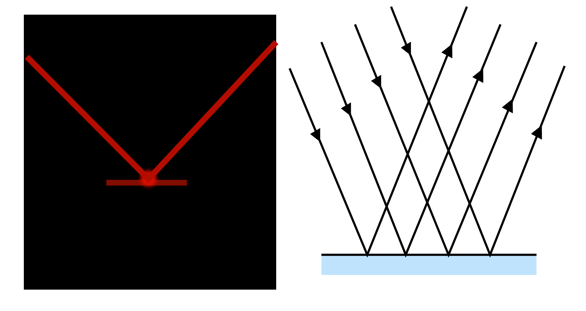
Regular Reflection
The perfect, mirror-like reflection of light is known as specular or regular reflection. Regular reflections include reflections in mirrors, water surfaces, and highly polished floors.
Irregular Reflection:
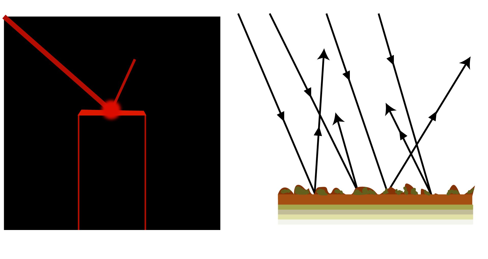
Irregular reflection, also known as diffused reflection, occurs when a ray of light strikes a rough or unpolished wall or wood. In this case, the incident light is reflected in different directions by different parts of the surface. There is no definite image formed in such cases, but the surface becomes visible. It is commonly referred to as light scattering. As a result of the diffused reflection, non-luminous objects become visible.
Reflection of Light by a Plane Surface:
The diagram depicts how a light ray is reflected by a plane surface. Assume MM' is a reflecting surface. When a light ray strikes MM' in the direction IO, it is reflected along the direction OR. The incident ray is denoted by IO, the point of incidence by O, and the reflected ray by OR.
Let ON be the perpendicular normal to the surface MM' at the point of incidence. The angle of incidence, denoted by the letter I is the angle formed by the incident ray with the normal at the point of incidence. The angle of reflection 'r' is the angle formed by the reflected ray and the normal at the point of incidence. A reflecting surface is something like a mirror.
Laws of Reflection:
The laws of reflection are observed to apply to any plane surface's reflection. The incident ray, reflected ray, and normal at the point of incidence all lie in the same plane, according to the laws of reflection. The angle of incidence equals the angle of reflection.
Nature of Image Formed By a Plane Reflecting Surface:
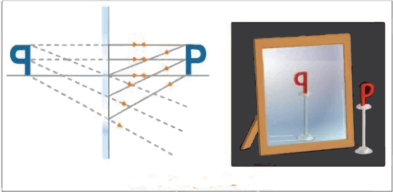
An image can be both real and virtual. When light rays intersect after reflection, a true image is formed. When the light rays after reflection do not actually intersect but appear to diverge from it, a virtual image is formed (these rays of light intersect when produced backwards).
Ray Diagrams of Plane Mirrors:
When drawing ray diagrams, the following rays are usually taken into account: A ray of light incident at 90 degrees on a plane mirror is reflected from the mirror along the same path. A ray of light falling at any angle on a plane mirror is reflected from it in such a way that the angle of incidence equals the angle of reflection. The image is formed when the reflected rays appear to collide.
Spherical Mirrors:
A spherical mirror is a mirror with a polished, reflecting surface that is part of a hollow sphere of glass or plastic. One of the two curved surfaces of a spherical mirror is coated with a thin layer of silver, followed by a coat of red lead oxide paint. As a result, one side of the spherical mirror is opaque, while the other is a highly polished reflecting surface. The opaque side of a mirror is always shaded in a diagram.
Please keep in mind that the opaque, non-reflecting side is shaded blue in the diagrams below, while the reflecting side is shaded red.
The spherical mirror is classified as follows based on the nature of its reflecting surface:
Concave Mirror
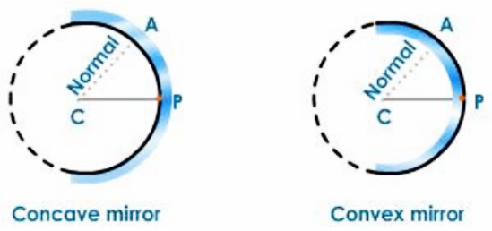
A concave mirror is a spherical mirror with its reflecting surface oriented toward the centre of the sphere of which it is a part.
Convex Mirror
A convex mirror is a spherical mirror with a reflecting surface that is angled away from the centre of the sphere of which it is a part.
Centre of Curvature:
The centre of curvature is the centre of the sphere, of which the spherical mirror is a part. It is represented by the letter C.
Radius of Curvature: The radius of the sphere, of which the mirror is a part, is defined as the radius of curvature. It is denoted by the letter R.
Linear Aperture: The distance between the extreme points (X and Y) on the mirror's periphery is defined as the linear aperture.
Pole: The pole is the spherical mirror's aperture's midpoint. It is denoted by the letter P.
Principal Axis
The principal axis of a spherical mirror is the straight line that passes through the pole and the centre of curvature.
Secondary Axis: A secondary axis is any radial line other than the principal axis that passes through the centre of curvature.
Normal: The normal at any point on the spherical mirror is the straight line formed by connecting that point to the mirror's centre. The normal at point A on the mirror is the line AC obtained by connecting A to the mirror's centre of curvature. The radius of the sphere of which the mirror is a part is equal to the normal at any point on a spherical mirror.
Principal Focus or Focus:
After reflection, light rays parallel to the principal axis of a mirror either pass through a point (in the case of a concave mirror) or appear to diverge from a point (in the case of a convex mirror), and this point is referred to as the mirror's principal focus or focal point.
Focal Length: The focal length of a mirror is the distance between the pole and the focus. It is symbolized by the letter f.
Characteristics of Focus of a Concave Mirror and a Convex Mirror
Convex Mirror | Concave Mirror |
The focal point is hidden behind the mirror. | The focus is on the mirror. |
Because the rays of light after reflection appear to come from the focus, the focus is virtual. | The focus exists because light rays converge at the focus after reflection. |
Sign Convention for Spherical Mirrors
In the ray diagrams of spherical mirrors, the following sign convention is used to measure various distances:
The object is always positioned to the left of the mirror.
All distances are measured from the mirror's pole.
Distances measured in the direction of the incident ray are positive, while distances measured in the opposite direction are negative.
Distances measured above the principal axis are positive, while distances measured below the principal axis are negative.
Concave Mirror
When an object is placed in front of a concave mirror, light rays from the object are reflected on the mirror. At the point where the reflected rays intersect or appear to intersect, an image is formed. The formation of an image by mirrors is typically depicted by drawing ray diagrams. To create a ray diagram, we need at least two rays with known paths after reflection from the mirror. These rays must be chosen based on our needs. To obtain the image, any two of the following rays can be considered.
After reflection from a concave mirror, a ray of light parallel to the principal axis passes through its focus.
After reflection, a ray of light passing through the focus of a concave mirror emerges parallel to the principal axis.
As the ray passing through the centre of curvature acts as a normal to the spherical mirror, a ray passing through the centre of curvature retraces its path after reflection.
According to the law of reflection, a ray of light striking the mirror at its pole is reflected.
Formation of Image by a Concave Mirror
When the Object Is At Infinity
When an object is placed at infinity, its rays are parallel to each other. Consider two rays, one striking the pole of the mirror and the other passing through the centre of curvature. The incident ray at the pole is reflected according to the law of reflection, and the second ray that passes through the mirror's centre of curvature retraces its path. After reflection, these rays form an image at the focus. The resulting image is accurate, inverted, and scaled down.
The image is at F
Real
Inverted
Diminished
When the Object Is Placed Beyond C
The two rays considered in order to obtain the image are:
A ray that passes through the centre of the curvature.
A ray that runs parallel to the principal axis.
After reflection, the ray passing through the centre of curvature retraces its path, and the ray parallel to the principal axis passes through the focus. After reflection, these rays intersect at a point between C and F.
The image is inverted, real, and shrunk. The image is:
Between C and F
Real
Inverted
Diminished
When the Object Is Placed At the Centre of Curvature
In this section, we will look at two rays, one parallel to the principal axis and the other passing through the focus. After reflection, the ray of light parallel to the principal axis passes through the focus. After reflection, the other ray that passes through the focus emerges parallel to the axis. Following reflection, these rays collide at the centre of curvature to form an inverted image that is real and the same size as the object.
The image is:
At C
Real
Inverted
Same size as object
When the Object is Between C and F
Consider a light ray parallel to the principal axis and another ray passing through the focus. The ray that is parallel to the principal axis passes through the principal focus and the ray that emerges parallel to the principal axis after reflection. The reflected rays collide at a point beyond C, resulting in a real, inverted, and magnified image.
The image is:
Beyond C
Real
Inverted
Magnified
When the Object is at the Focus
Consider a light ray parallel to the principal axis and another ray passing through the centre of curvature. The ray parallel to the principal axis passes through the focus, while the ray through the centre of curvature retraces its path. The reflected rays are parallel to each other and would only meet at infinity, implying that the image is formed at infinity and is a true, inverted, and enlarged image.
The image is at infinity:
Real
Inverted
Magnified
When the Object Is Between the Pole and the Focus
Consider a ray of light parallel to the principal axis and another ray passing through the centre of curvature. After reflection, the ray that passes through the centre of curvature retraces its path, and the other ray that is parallel to the principal axis passes through the focus. When the reflected rays are extended backwards, these rays appear to meet behind the mirror. The image is erect, virtual, and magnified.
The image is:
Behind the mirror
Virtual
Erect
Magnified
Uses of Concave Mirrors
Concave mirrors are used to obtain a parallel beam of light in the following applications: as reflectors in car headlights, searchlights in torches, and so on. The light source is positioned at the concave reflector's focus for this purpose.

Fig. Headlight of Car
Light is focused on the tooth to be examined by the dentist.

As shaving and make-up mirrors to obtain an enlarged erect image of the face

Solar radiations are concentrated in solar heating devices. The food or substance to be heated is placed in the centre of a large concave reflector for this purpose. Sunlight converges on the substance after reflection and heats it.
Convex Mirror
When creating ray diagrams, the following rays are taken into account. After reflection from a convex mirror, a ray of light travelling parallel to the principal axis appears to come from its focus behind the mirror.
A ray of light travelling towards the mirror's centre of curvature hits the mirror at 90o and is reflected along its path.
A ray of light directed towards the principal focus of a convex mirror will emerge parallel to the principal axis after reflection.
According to the laws of reflection, a ray of light incident obliquely to the principal axis and directed towards the pole of the mirror is reflected.
Regardless of the position, a convex mirror always produces a virtual image.
Formation of Image in a Convex Mirror
When the Object Is Placed Between Infinity and the Pole of the Mirror
The image is:
Formed between the pole and the focus
Erect
Diminished
Virtual
When the Object Is At Infinity
The image is:
Formed at the focus
Extremely diminished
Virtual
Erect
Uses Of Convex Mirror
A rear-view mirror in a car. This convex mirror provides the driver with a clear view of approaching traffic from behind because convex mirrors are curved outwards, providing a wider field of view.

In department stores, there is a vigilance mirror.
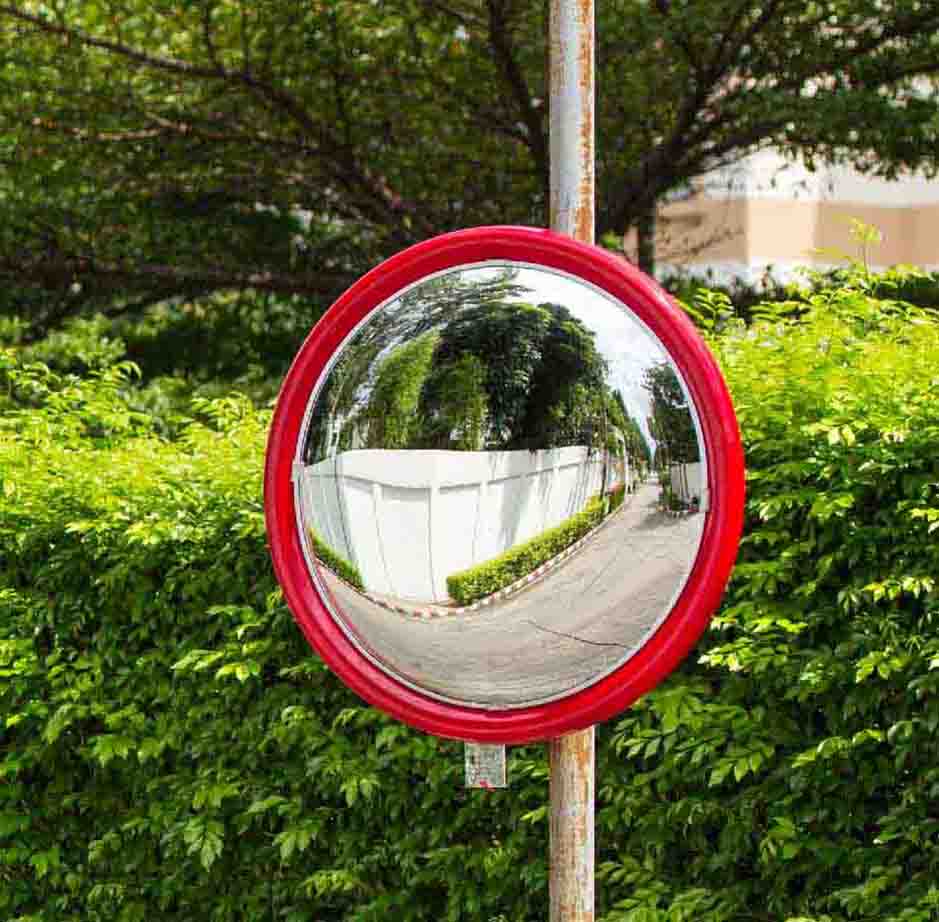
Reflectors are used in street lamps to divert light over a large area.
Position of Object | Position of Image | Size of the Image | Nature of the Image |
At infinity | At focus | Extremely diminished | Virtual and erect |
Between infinity and pole of the mirror | Between the focus and pole | Diminished | Virtual and erect |
Mirror Formula
$\frac{1}{f}=\frac{1}{v}+\frac{1}{u}$
Here, $u$ is the Object distance, $v$ is the Image distance and $f$ is the Focal length.
Magnification
The magnification produced by a spherical mirror indicates the extent to which an object's image is magnified in relation to the object's size.
Magnification is defined as the ratio of the image's height to the object's height. The letter m is commonly used to represent it.
If h is the object's height and h' is the image's height, then the magnification m produced by a spherical mirror can be written as
$m=\frac{h^{\prime}}{h}$
The magnification $\mathrm{m}$ is also related to the object distance $(\mathrm{u})$ and image distance (v). It can be expressed as:
$m=\frac{h^{\prime}}{h}=-\frac{v}{u}$
The negative sign in the value of the magnification indicates that the image is real. A positive sign in the value of the magnification indicates that the image is virtual.
Refraction: The deviation in the path of light when it passes from one medium to another medium of different density is called refraction.
The twinkling of stars is due to atmospheric refraction of starlight. Since light bends towards the normal the apparent position of the star is slightly different from its actual position as it passes through the atmosphere. Hence the star appears slightly higher than its actual position. Due to changing condition of earth's atmosphere the apparent position of the star changes slightly and the intensity of light reaching the eye also fluctuates. This gives rise to the twinkling effect of the star.
Incident Ray (IO)
The ray of light striking the surface of separation of the media through which it is traveling is known as the incident ray.
Point of Incidence (O)
The point at which the incident ray strikes the surface of separation of the two media is called the point of incidence.
Normal (N)
The perpendicular drawn to the surface of separation at the point of incidence is called the normal.
Refracted Ray (OR)
The ray of light which travels into the second medium, when the incident ray strikes the surface of separation between the media 1 and 2, is called the refracted ray.
Angle of Incidence (i)
The angle which the incident ray makes with the normal at the point of incidence is called angle of incidence.
Angle of Refraction (r)
The angle which the refracted ray makes with the normal at the point of incidence is called angle of refraction. A ray of light refracts or deviates from its original path as it passes from one optical medium to another because the speed of light changes.
Laws of Refraction
The incident ray, the refracted ray and the normal to the surface at the point of incidence all lie in one plane. For any two given pairs of media, the ratio of the sine of the angle of incidence to the sine of the angle of refraction is constant. The above law is called Snell's law after the scientist Willebrod Snellius who first formulated it
Thus,
$\frac{\sin i}{\sin r}=\text { a constant }=\mu$
Where µ is the refractive index of the second medium with respect to the first medium.
The refractive index of glass with respect to air is given by the relation.
In general, if a ray of light is passing from medium 1 to medium 2, then
If the medium 1 is air or vacuum, the refractive index of medium 2 is referred to as the absolute refractive index. The refractive index of a medium depends on the following factors: The nature of the medium. The colour or wavelength of the incident light.
Refraction of Light through a Glass Slab
When a ray of light passes from air to glass, that is, from a rarer medium to a denser medium, the refracted ray bends towards the normal drawn at the point of incidence. In this case angle of i > angle of r. But when the ray of light is passing from glass to air, that is, from a denser medium to a rarer medium the refracted ray bends away from the normal. In this case angle of r > angle of i. The emergent ray, O1E which is nothing but the refracted ray emerging out of the glass slab is parallel to the incident ray. This means that the refracted ray (emergent ray) has been displaced from its original path by a distance XY. This displacement is referred to as lateral displacement.
Lenses
A lens is a portion of a transparent refracting medium bounded by two generally spherical or cylindrical surfaces, or one curved and one plane surface. Convex lenses and converging lenses are the two types of lenses.
Convex Lens
A convex lens is one that is thicker in the centre and thinner at the edges. A convex lens has at least one surface that bulges out in the middle. Convex lenses are classified as bi-convex or double-convex, plano-convex lens and concavo-convex lenses based on their shape.
Concave Lens
A concave lens is one that is thinner in the centre and thicker at the edges. These lenses, like convex lenses, are classified as:
bi-concave
Plano - concave
convexo - concave
Terminology Used in Optics
Optical Centre
It is the focal point of a lens. It is represented by the letter O. A ray of light passing through the optical centre of a lens does not deviate in any way. It is also known as an optic centre.
Principal Axis
The principal axis is the straight line that connects the centres of curvature of a lens's two curved surfaces.
Principal Foci
Rays of light can pass through the lens in any direction, so there will be two principal foci on either side of the lens, which are referred to as the first and second principal foci of a lens, respectively.
First Principal Focus (F1)
It is a point on the lens's principal axis where light rays starting from it (convex lens) or appearing to meet at the point (concave lens) become parallel to the lens's principal axis after refraction from the two surfaces of the lens.
The distance between the optic centre and the first focus is referred to as the lens's first focal length (f1).
Second Principal Focus (F2)
It is a point on the lens's principal axis at which light rays parallel to the lens's principal axis after refraction from both surfaces of the lens pass through (convex lens) or appear to come from this point (concave lens).
The distance between the optic centre and the second principal focus is referred to as the lens's second focal length (f2). The first and second focal lengths will be equal if the medium on both sides of the lens is the same. The focus of a convex lens is physical, whereas the focus of a concave lens is virtual.
Sign Convention for Spherical Lenses
All distances are measured from the lens's optical centre. Distances measured in the direction of the incident light are considered positive, while distances measured in the opposite direction of the incident light are considered negative. All measurements taken above the principal axis are considered positive, while measurements taken below the principal axis are considered negative, i.e., object height is always considered positive, while image height is only considered positive for virtual images.
Formation of Image by a Convex Lens
A ray of light passing through the lens's optical centre travels straight and without deviation. Only in the case of a thin lens does this hold true.
After refraction, an incident ray parallel to the principal axis passes through the focus.
After refraction, an incident ray passing through the focus of a lens emerges parallel to the principal axis.
When the Object is Placed between F1 and O
The image is:
Formed behind the object
Virtual
Erect
Magnified
When the Object is placed at 2F1
The image is:
Formed at 2F2
Real
Inverted
Same size as the object
When the Object is placed Between F1 and 2F1
The image is:
Formed beyond 2F2
Real
Inverted
Magnified
When the Object is placed at F1
The image is:
formed at infinity
real
inverted
magnified
When the Object is placed beyond 2F1
The image is: formed between F2 and 2F2 real inverted diminished.
When the Object is placed at Infinity
When the object is at infinity, the rays coming from it are parallel to each other. The image is:
formed at F2 inverted
real
highly diminished
Convex lenses are also used in spectacles to correct the vision problem of hypermetropia.
Formation of Image by a Concave Lens
After refraction, an incident ray of light from an object parallel to the principal axis of a concave lens appears to come from its focus.
An incident ray of light that passes through the optical centre exits the lens with no deviation.
Whatever the object's position, a concave lens always produces a virtual, erect, and diminished image. Let us now draw ray diagrams to show where the images are when the object is placed - at infinity, between O and F1, and anywhere between infinity and O.
When the Object is at Infinity
The image is: formed at F1 erect virtual diminished.
When the Object is Placed at Any Position Between O and Infinity
The image is: formed between O and F1 erect virtual diminished
Uses of Concave Lens
It is used to correct myopia in spectacles.
It is used in conjunction with a convex lens to correct flaws such as chromatic and spherical aberration (the failure of rays to converge at one focus because of a defect in a lens or mirror).
Sign Convention for Lenses
For measuring various distances, the following sign convention is used:
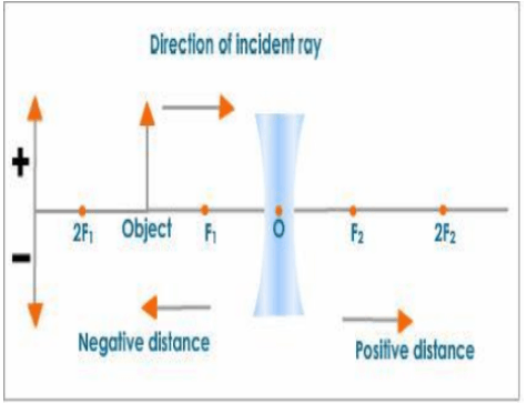
All distances on the principal axis are measured from the optical centre.
Distances measured in the direction of incident rays are positive, while distances measured in the opposite direction of incident rays are negative.
All measurements taken above the principal axis are positive. As a result, the height of an object and the height of an erect image are both positive, while all distances measured below the principal axis are negative.
Note:
The rules are the same as for spherical mirrors.
The sign convention for lenses is shown in the table below:
For measuring various distances, the following sign convention is used:
The optical centre is used to measure all distances along the principal axis. Distances measured in the direction of incident rays are positive, while distances measured in the opposite direction of incident rays are negative. All measurements taken above the principal axis are positive. As a result, the height of an object and the height of an erect image are both positive, while all distances measured below the principal axis are negative.
Lens Formula
The lens formula or lens equation describes the relationship between the object's distance (u), the image's distance (v), and the focal length (f) of the lens.
$\frac{1}{f}=\frac{1}{v}-\frac{1}{u}$
This lens formula works for both convex and concave lenses.
Note: Things to keep in mind when using the lens formula. The known parameter values should be used with their proper sign according to the sign convention. During calculations, the unknown parameter should not be given a sign.
Magnification
Magnification is defined as the ratio of image size (hI) to object size (ho).
Depending on the size and nature of the image, the magnification produced by a lens can be equal to one, greater than one, or less than one.
Case I
When the image's height (hI) equals the object's height (ho).
$\mathrm{m}=\frac{\mathrm{h}_{\mathrm{I}}}{\mathrm{h}_{\mathrm{o}}}=1$
As a result, when the magnification is set to one, the size of the image is the same as the size of the object.
Case II
When the image's height $\left(\mathrm{h}_{1}\right)$ is greater than the object's height $\left(\mathrm{h}_{\mathrm{o}}\right)$.
$\mathrm{m}=\frac{\mathrm{h}_{\mathrm{I}}}{\mathrm{h}_{\mathrm{o}}}>1$
The image is magnified.
Case III
When the image's height $\left(h_{1}\right)$ is lesser than the object's height $\left(h_{0}\right)$.
$\mathrm{m}=\frac{\mathrm{h}_{\mathrm{I}}}{\mathrm{h}_{\mathrm{o}}}<1$
The image is diminished.
The height of the object is always positive for both types of lenses, whereas the height of the image can be + or - depending on its nature. The height of an inverted and real image is negative according to lens sign convention, and thus the magnification of a lens is negative when it produces an inverted and real image. The image's height is positive for an erect and virtual image. When an erect and virtual image is formed, the magnification is positive.
Power of a Lens
A ray of light bends whenever it passes through a lens (except when it passes through the optical centre). Convergence is the bending of light rays towards the principal axis, and divergence is the bending of light rays away from the principal axis. The power of a lens expresses its degree of convergence or divergence. A lens with a short focal length deviates the rays more than a lens with a long focal length. As a result, a lens's power is defined as the reciprocal of its focal length in meters.
$\text { Power of a lens }=\frac{1}{\text { Focal length in metres }}$
The unit of power is dioptre.
If a convex lens has a power of one D, its focal length is one meter.
Important Questions from CBSE Class 10 Science Chapter 9 - Light Reflection and Refraction
The focal length of a concave lens is 20 cm. From the lens, at what distance should a 5 cm tall object be placed to form an image that is at 15 cm from the lens? Also, detemine the size of the image that is formed.
Explain the meaning of the statement “The refractive index of diamond is 2.42.” with respect to the speed of light.
When a pencil is partly immersed in water, it appears to be bent at the water surface. Explain this with the help of a diagram.
When a ray of light travels from one medium to another, why does it bend?
Important Topics of Science Class 10 Chapter 9 You Shouldn’t Miss!
S.No. | Important Topics |
1. | Reflection of Light |
2. | Image Formation by Spherical Mirrors |
3. | Representation of image by spherical mirror using ray diagrams |
4. | Mirror Formula and Magnification |
5. | Refraction of Light |
6. | Lens Formula and Magnification |
Important formula in Class 10 Science Chapter 9 Light Reflection and Refraction
1. Mirror Formula (For Spherical Mirrors):
$\frac{1}{f} = \frac{1}{v} + \frac{1}{u}$
Where:
f = Focal length of the mirror
v = Image distance from the mirror
u = Object distance from the mirror
2. Magnification Formula (For Mirrors):
$m = \frac{h_i}{h_o} = \frac{-v}{u}$
Where:
m = Magnification
$h_i$ = Height of the image
$h_o$ = Height of the object
v = Image distance from the mirror
u = Object distance from the mirror
3. Lens Formula (For Spherical Lenses):
$\frac{1}{f} = \frac{1}{v} - \frac{1}{u}$
Where:
f = Focal length of the lens
v = Image distance from the lens
u = Object distance from the lens
4. Magnification Formula (For Lenses):
$m = \frac{h_i}{h_o} = \frac{v}{u}$
Where:
m = Magnification
$h_i$ = Height of the image
$h_o$ = Height of the object
v = Image distance from the lens
u = Object distance from the lens
5. Refractive Index Formula:
$n = \frac{\text{Speed of light in vacuum (c)}}{\text{Speed of light in the medium (v)}}$
Where:
n = Refractive index of the medium
c = Speed of light in vacuum
v = Speed of light in the medium
Importance of Class 10 Science Light Reflection and Refraction Notes
Class 10 Science Light Reflection And Refraction Notes simplify complex concepts like how light reflects off surfaces and refracts through different mediums, making them easier to understand.
Understanding light reflection and refraction is crucial for everyday applications like how mirrors and lenses work in glasses, cameras, and telescopes.
Class 10 Science Chapter 9 Notes provide key formulas and examples, which are essential for solving problems in exams.
Learning these concepts helps students grasp the functioning of optical instruments, which is important for both academic and practical knowledge.
Light Reflection And Refraction Class 10 Notes PDF also breaks down the laws of reflection and refraction in simple terms, aiding in better retention and recall during tests.
Mastering this chapter helps build a foundation for future topics in physics, such as optics and wave theory.
Class 10 Science Chapter 9 Notes are valuable for revision, as they provide a concise summary of all key points and help students focus on important areas.
Tips for Learning the Class 10 Chapter 9 Science Light Reflection and Refraction
Start by understanding the basic concepts of reflection and refraction, including how light behaves when it hits surfaces or passes through different mediums.
Memorise key formulas, such as the mirror formula and lens formula, as they are crucial for solving numerical problems.
Practice drawing ray diagrams for mirrors and lenses. This will help you visualise how images are formed and better understand the concepts.
Pay attention to the sign conventions for mirrors and lenses, as using the correct signs is important when solving problems.
Solve a variety of problems related to both convex and concave mirrors and lenses to get comfortable with different types of questions.
Relate the concepts to real-life examples, like how a spoon acts as a curved mirror or how eyeglasses use lenses to correct vision.
Regularly revise the refractive index formula and understand how it explains why light bends when passing from one medium to another, like air to water.
Conclusion:
Chapter 9 of Class 10 Science, Light: Reflection and Refraction, covers essential concepts that help us understand how light behaves when it bounces off surfaces or passes through different materials. By learning about mirrors, lenses, and the bending of light, students can grasp the science behind everyday things like cameras, glasses, and even how we see ourselves in the mirror. Mastering the key formulas, practising ray diagrams, and applying these concepts to real-life situations makes this chapter easier to understand and prepares students for their exams with confidence.
Related Study Materials for Class 10 Science Chapter 9 Light Reflection and Refraction
Students can also download additional study materials provided by Vedantu for Science Class 10, Chapter 9–
S.No | Study Material Links for Light Reflection and Refraction Class 10 |
1. | Class 10 Light Reflection and Refraction Important Questions |
2. | |
3. | Class 10 Light Reflection and Refraction NCERT Exemplar Solutions |
Chapter-wise Links for Science Class 10 Notes
S. No | CBSE Class 10 Revision Notes Links |
1 | |
2 | |
3 | |
4 | |
5 | |
6 | |
7 | |
8 | |
9 | |
10 | |
11 | |
12 |
Important Study Materials for Class 10 Science
S. No | Related Links for Class 10 Science |
1. | |
2. | |
3. | |
4. | |
5. |
FAQs on Light Reflection And Refraction Class 10 Science Chapter 9 CBSE Notes - 2025-26
1. What are the most important summary points to remember from Class 10 Science Chapter 9 – Light Reflection and Refraction?
Key points include understanding reflection and refraction of light, laws governing them, image formation in different types of mirrors and lenses, and applying formulas like the mirror formula, lens formula, and magnification. Also, knowing the sign convention for mirrors and lenses, and the practical uses of concave and convex mirrors and lenses, is vital for quick revision.
2. What are some effective strategies for revising the Light Reflection and Refraction chapter for exams?
Begin with concept maps of mirror and lens types, memorize key formulas, practice drawing ray diagrams, focus on the laws of reflection and refraction, and solve a variety of numericals. Regular revision of key terms and connecting them to real-life applications (like eyeglasses or headlights) will help reinforce memory.
3. How should I quickly revise ray diagram concepts for spherical mirrors and lenses?
First, understand the principal rays used for each case. Then, draw step-by-step ray diagrams showing image formation when the object is placed at different positions relative to the mirror/lens (C, F, P for mirrors; F1, F2, O for lenses). Mark nature, orientation, and size of the image for each scenario. Reviewing tables summarizing image characteristics is also helpful for rapid recall.
4. Why is understanding sign conventions important in solving numerical problems on light reflection and refraction?
Using the correct sign convention ensures you choose the right values for object distance, image distance, and focal length when applying mirror and lens formulas. Incorrect signs can lead to wrong results for the nature and position of the image. Always refer to the sign rules: distances measured in the direction of incident light are positive, and measurements opposite are negative.
5. What are the key formulas in Light Reflection and Refraction Class 10 Notes and how can they be applied during revision?
- Mirror Formula: 1/f = 1/v + 1/u
- Magnification (Mirror): m = h'/h = -v/u
- Lens Formula: 1/f = 1/v - 1/u
- Magnification (Lens): m = h'/h = v/u
- Refractive Index: n = c/v (c = speed of light in vacuum, v = speed in medium)
6. Can you provide a quick summary concept map covering the difference between concave and convex mirrors?
- Concave mirror: Inner surface is reflective; can form real or virtual images; focus is in front of the mirror; used in headlights, shaving mirrors.
- Convex mirror: Outer surface is reflective; forms only virtual and diminished images; focus is behind the mirror; used in vehicle rear-view mirrors for wider field of view.
7. How do you connect the concepts of reflection and refraction to real-life situations during revision?
Connect reflection to examples like seeing yourself in a mirror, using rear-view mirrors, or headlights of vehicles. Refraction explains phenomena like why a pencil appears bent in water, operation of lenses in eyeglasses, cameras, and microscopes. Linking such daily applications to each formula or principle aids both understanding and retention.
8. What are common mistakes to avoid while revising this chapter?
- Ignoring the sign convention in numericals
- Confusing the differences between concave/convex mirror and lens behaviors
- Forgetting to label principal axis, focus, centre of curvature in ray diagrams
- Not practicing enough questions based on application and reasoning
- Mixing up the formulas for mirrors and lenses
9. Why is mastering this chapter important for further physics studies?
Light reflection and refraction lay the foundation for more advanced topics in optics in higher secondary and competitive exams. Concepts like image formation, power of lens, and optical instruments build directly on the basics covered here. Mastery ensures easier understanding of complex physics topics later on.
10. How can revision notes help in last-minute exam preparation for Light Reflection and Refraction?
Revision notes provide a condensed summary of core concepts, formulas, and diagrams. These are ideal for quick recaps before exams, ensuring you remember the most crucial points, equations, and ray diagrams without going through lengthy textbooks. Using structured notes can greatly enhance recall and confidence just before the test.


 Watch Video


