


How to Write Step-by-Step Answers for Class 7 Science Ch 3: Electricity and Circuits
Question 1.
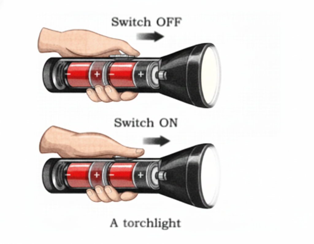
Why does the torch lamp glow in one position of its switch? (Page 24)
Answer:
The torch lamp lights up when the switch is in the “ON” position because the electrical circuit is completed, allowing current to pass through the lamp. When the switch is in the “OFF” position, the circuit remains open, preventing the flow of current, and therefore the lamp does not glow.
Question 2.
In a torch, we generally use more than one cell. Are those placed in any particular order? (Page 25)
Answer: Yes, the cells in a torch are generally connected in series. In this arrangement, the positive terminal of one cell is linked to the negative terminal of the next cell. This setup increases the overall voltage, providing enough power for the lamp to glow.
Question 3.
How does a switch turn ‘ON’ or ‘OFF’ the torchlight? (Page 32)
Answer: The switch regulates the flow of electric current in a circuit. When it is in the “ON” position, the circuit is closed, allowing electricity to pass through the lamp and light it up. When the switch is in the “OFF” position, the circuit opens, the flow of electricity stops, and the lamp turns off.
Question 4.
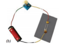
Can we represent the circuit in a simpler manner? (Page 33)
Answer: Yes, electrical circuits and their components are represented using standard symbols in circuit diagrams. For instance, a battery is shown by a pair of parallel lines—one long and one short—while a lamp is represented by a circle with an ‘X’ inside it.
Question 5.
Why did we use metal wire for making the electric circuit? Can we not use some other material for the wires? (Page 34)
Answer: Metal wires, commonly made of copper, are used because metals are excellent conductors of electricity and allow current to flow easily. Other materials may be used, but they do not conduct electricity as efficiently. For instance, rubber and plastic are insulators and therefore cannot carry electric current.
Question 6.
Why are electric wires covered with plastic or rubber? (Page 34)
Answer: Electric wires are coated with plastic or rubber because these materials act as insulators. They stop the electric current from leaking out and protect people from electric shocks. The insulation also prevents wires from coming into contact with each other, reducing the risk of short circuits.
Let Us Enhance Our Learning
Question 1.
Choose the incorrect,statement.
(i) A switch is the source of electric current in a circuit.
(ii) A switch helps to complete or break the circuit.
(iii) A switch helps us to use electricity as per our requirement.
(iv) When the switch is in ‘OFF’ position, there is an air gap between its terminals.
Answer:
(i) A switch is the source of electric current in a circuit.
Question 2.
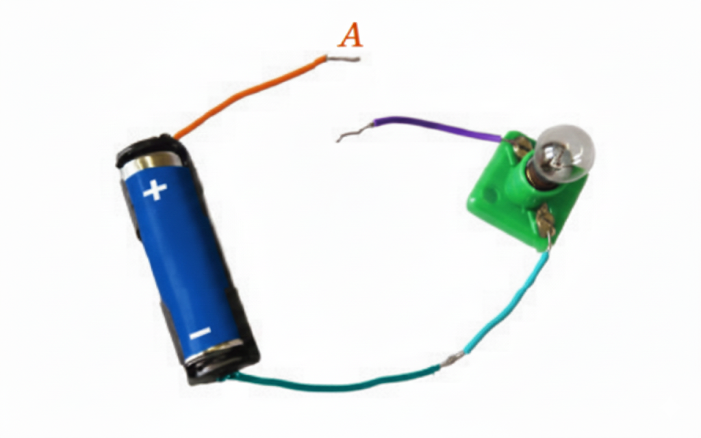
Observe Fig. 3.16. With which material connected between the ends A and B, the lamp will not glow?
Answer:
To stop the lamp from glowing in Fig. 3.16, place an insulating material such as rubber or plastic between points A and B. This will break the circuit and prevent the flow of electric current.
Question 3.
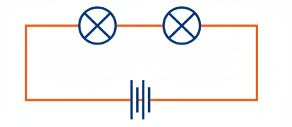
In Fig. 3.17, if the filament of one of the lamps is broken, will the other glow? Justify your answer.
Answer:
In Fig. 3.17, the lamps are connected one after the other, as shown in the circuit diagram. If the filament of any one lamp breaks, the other lamp will also stop glowing. This happens because, in a series (line) circuit, electric current must pass through each component in sequence. When one component is damaged, the circuit breaks and current cannot flow through the remaining parts.
Question 4.
A student forgot to remove the insulator covering from the connecting wires while making a circuit. If the lamp and the cell are working properly, will the lamp glow?
Answer: No, the lamp will not glow in this situation. The insulating coating on the connecting wires blocks the flow of electric current. Because the current cannot pass through the insulated portions, the circuit stays incomplete and the lamp does not light up.
Question 5.
Draw a circuit diagram for a simple torch using symbols for electric components.
Answer:

Question 6.
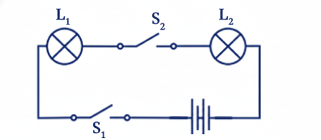
(i) If S2 is in ‘ON’ position, S1 is in ‘OFF’ position, which lamp(s) will glow?
(ii) If S2, is in ‘OFF’ position, S1, is in ‘ON’ position, which lamp(s) will glow?
(iii) If Si; and S2, both are in ‘ON’ position, which lamp(s) will glow?
(iv) If both S1, and S2, are in ‘OFF’ position, which lamp(s) will glow?
Answer:
(i) S2 ‘ON’, St ‘OFF’: Lamp L2 will glow.
(ii) S2 ‘OFF’, St ‘ON’: Lamp L1 will glow.
(iii) S1 ‘ON’, S2 ‘ON’: Both lamps (L1 and L2) will glow.
(iv) S1 ‘OFF’, S2 ‘OFF’: Neither lamp will glow.
Question 7.
Vidyut has made the circuit as shown in Fig. 3.19. Even after closing the circuit, the lamp does not glow. What can be the possible reasons? List as many possible reasons as you can for this faulty operation. What will you do to find out why the lamp did not glow?
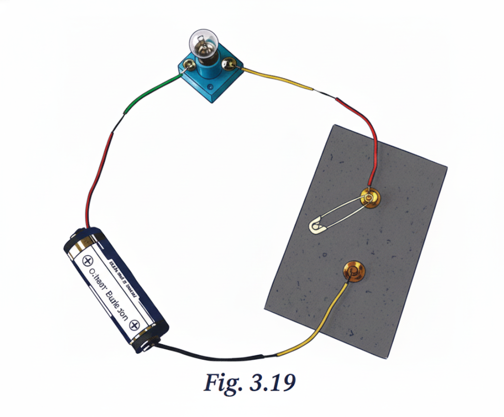
Answer:
Reasons:
(a) Loose Connections: Make sure all wires are firmly connected to the battery, lamp, and switch.
(b) Burnt-out Bulb: Try replacing the bulb with a new one to check if the old bulb is faulty.
(c) Dead Battery: Verify whether the battery is supplying power by testing it with a multimeter.
(d) Faulty Switch: Check the switch by bypassing it and directly connecting the wires to see if the lamp glows.
Question 8.
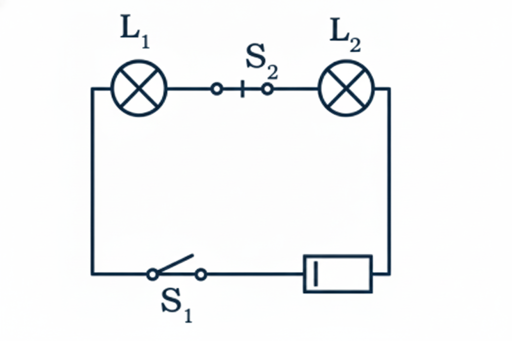
In Fig. 3.20, in which case(s) the lamp will not glow when the switch is closed?
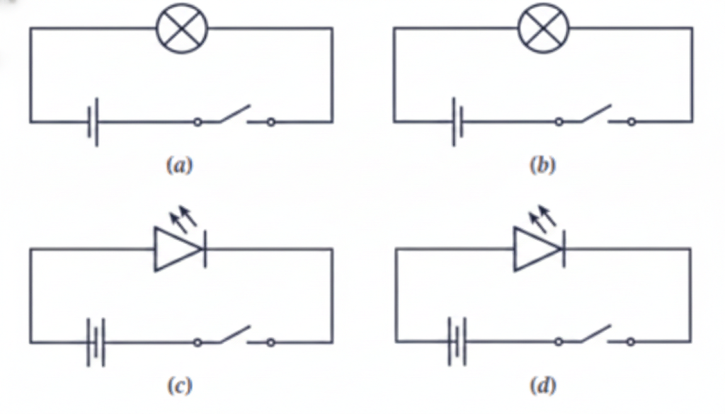
Answer:
Case (a): The lamp will glow.
Case (b): The lamp will not glow.
Case (c): The lamp may not glow if the battery is connected in reverse.
Case (d): The lamps will glow.
Question 9.
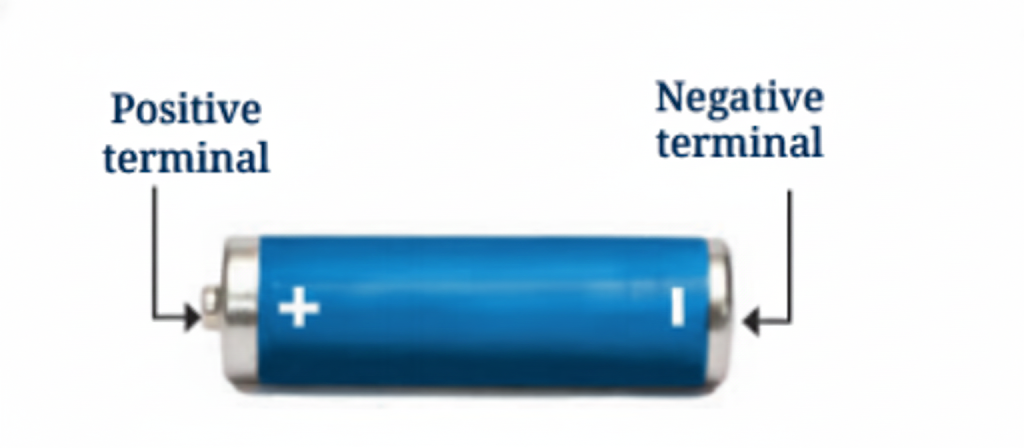
Suppose the ‘+’ and symbols cannot be read on a battery. Suggest a method to identify the two terminals of this battery.
Answer: Use a circuit by connecting the battery to a light bulb. If the connection is correct, the bulb will glow brightly.
Also, check the battery’s shape: the flat end generally represents the negative (–) terminal, while the raised or protruding end indicates the positive (+) terminal.
Question 10.
You are given six cells marked A, B, C, D, E, and F. Some of these are working and some are not. Design an activity to identify which of them are working.
(i) List the items that you require.
(ii) Write the procedure that you will follow.
(iii) With the items, carry out the activity to identify the cells that are working.
Answer:
(i) Items Required:
Light bulb
Connecting wires
Cells (A, B, C, D, E, F)
(ii) Procedure:
Connect the light bulb to a single cell.
Observe whether the bulb lights up. If it glows, the cell is in good condition.
Repeat the same steps for each of the cells A, B, C, D, E, and F.
(iii) Carrying Out the Activity:
Test each cell one at a time by connecting it to the bulb.
Cells that make the bulb glow are working properly, while those that do not are not functioning.
Question 11.
An LED requires two cells in series to glow. Tanya made the circuit as shown in Fig. 3.21. Will the lamp glow? If not, draw the wires for correct connections.
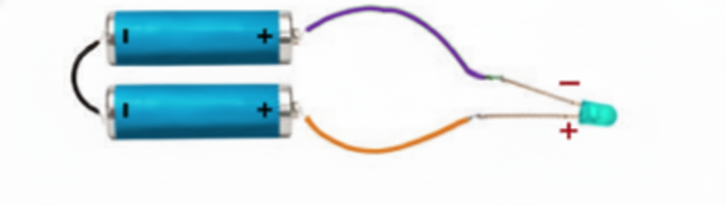
Answer:
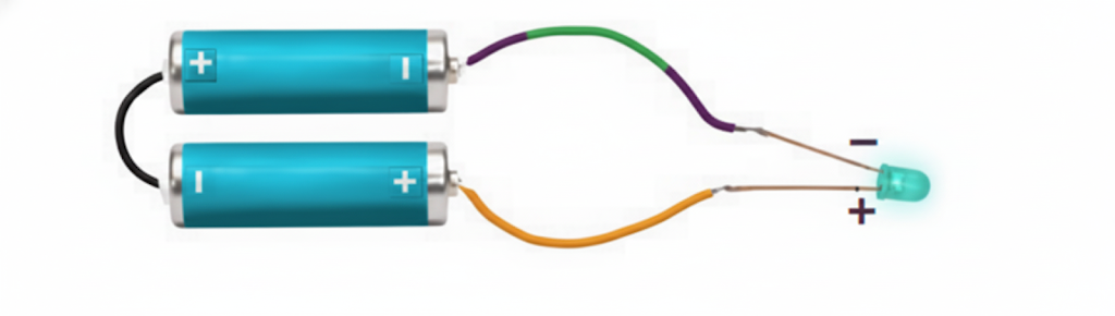
The LED bulb will glow only when it is connected correctly—that is, when the longer wire (the positive terminal of the LED) is connected to the positive terminal of the battery, and the shorter wire (the negative terminal) is connected to the negative terminal of the battery.
According to the given connection, the LED will not glow because the negative terminal of the LED is connected to the positive terminal of the battery. The correct connection should be:
Activity 3.1: Let Us Explore (Page 24)
Observation and Conclusion:
The torchlight glows when the switch is switched on because the electric cells inside supply energy to the lamp. When the switch is turned off, the circuit is broken and the lamp does not light up. This demonstrates that electric current can flow only when the circuit is complete.
Activity 3.2: Let Us Observe (Page 25)
Conclusion:
An electric cell has two terminals—a positive terminal marked by a metal cap and a negative terminal in the form of a metal disc. These terminals allow electric current to flow through a circuit. An electric cell serves as a portable source of electrical energy.
Activity 3.3: Let Us Experiment (Page 25)

Observation and Conclusion:
The torchlight glows only when the cells are arranged properly, with the positive terminal of one cell connected to the negative terminal of the next. This correct arrangement forms a battery, enabling the flow of electric current and causing the lamp to glow.
Activity 3.4: Let Us Observe (Page 26)
Observation and Conclusion:
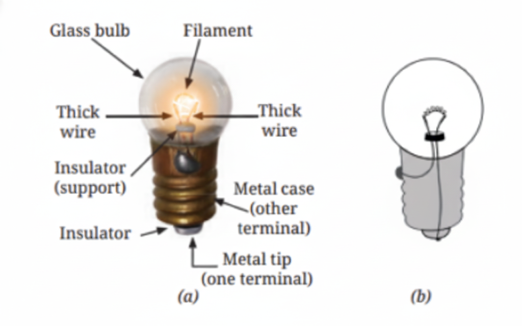
The part of an incandescent lamp that glows is a thin wire known as the filament. When electric current passes through it, the filament becomes very hot and emits light. It is attached to two thicker wires that serve as terminals, and these wires are arranged so that they do not touch each other inside the lamp.
Activity 3.5: Let Us Observe (Page 27)
Observation and Conclusion:
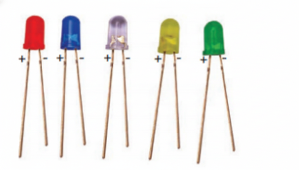
LEDs do not contain a filament like incandescent bulbs. They have two terminals—a longer wire that acts as the positive terminal and a shorter wire that acts as the negative terminal. An LED glows only when it is connected correctly to a battery. Some torch lamps use LEDs that come in different shapes and colours.
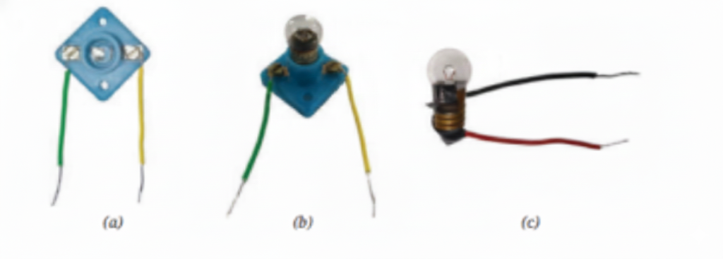
Fig. 3.7 (a) An electric cell holder with two wires attached (b) An electric cell inside the cell holder (c) Wires connected to an electric cell using electrical tape
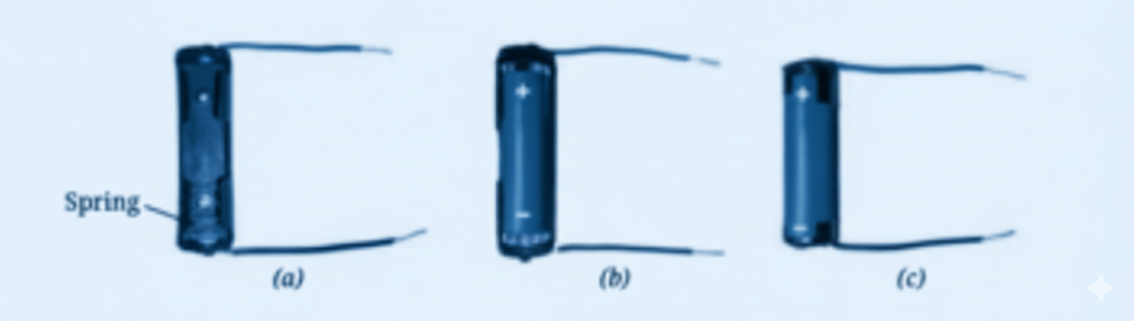
Fig. 3.8 (a) An electric lamp holder with wires attached (b) An incandescent lamp inside the lamp holder (c) Wires connected to incandescent torch lamp with electrical tape
Table 3.1: Trying to Make the Lamp Glow
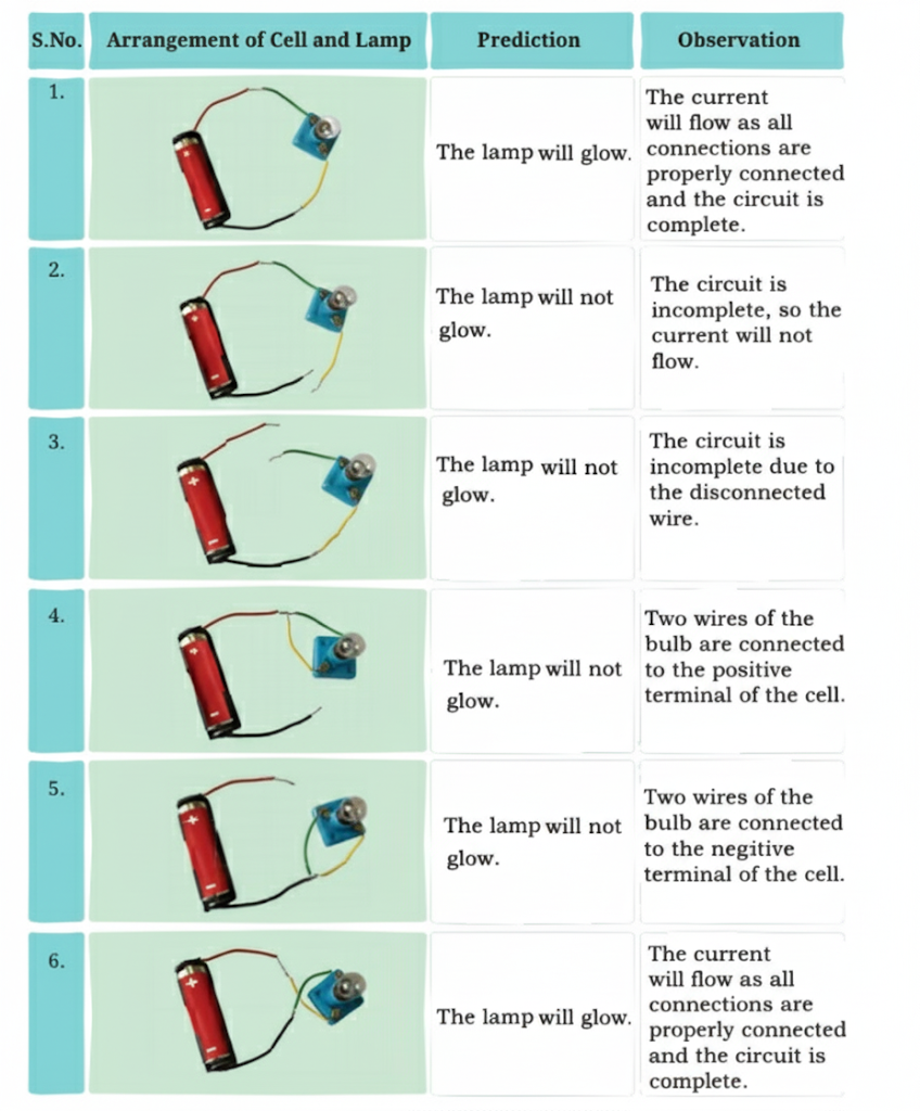
Observation and Conclusion:
An electric lamp glows only when electric current flows through the circuit. Current can flow only when all the connections are properly made and the circuit is complete. If the connections are incorrect or the circuit is incomplete, current will not flow and the lamp will not glow.
Activity 3.7 Let Us Experiment (Pages 30-31)
Observation and Conclusion:
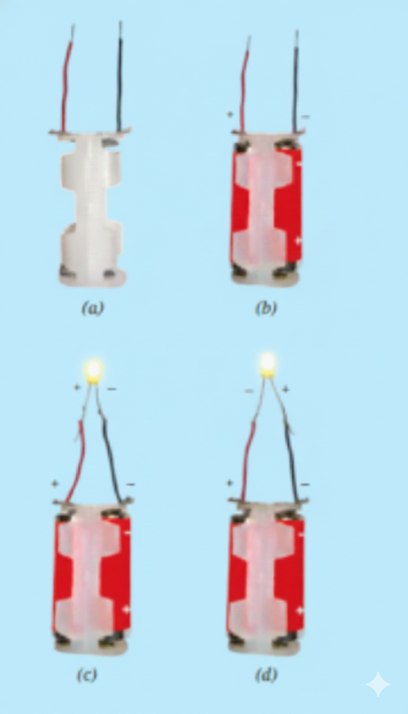
The LED glows only when it is connected correctly, with the longer wire attached to the positive terminal and the shorter wire connected to the negative terminal of the battery, as shown in Fig. (a). This indicates that electric current flows in only one direction through an LED. When the connections are reversed, the LED does not light up. This observation helps us understand the correct way to connect components in an electric circuit.
Activity 3.8 Let us Test (Page 32)
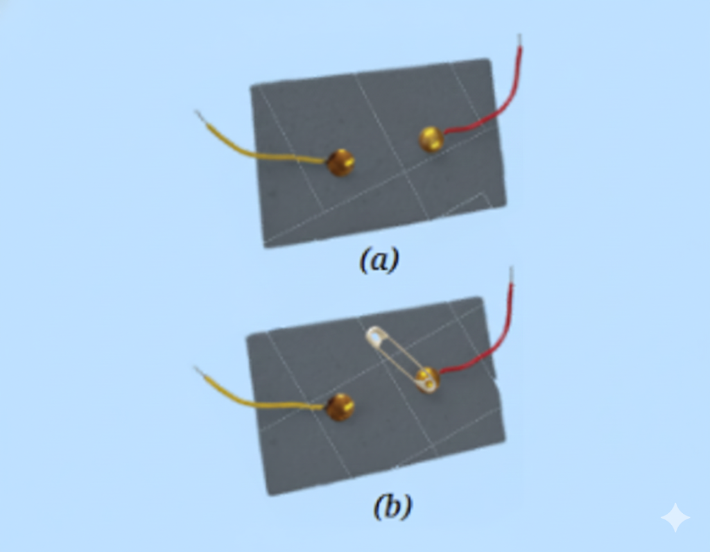
Observation and Conclusion:
We made a simple switch using a safety pin and drawing pins fixed on a piece of cardboard. When connected with wires, this arrangement functions as a basic switch that can open or close an electric circuit.
Activity 3.9 Let Us Test (Page 32)
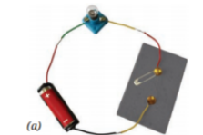
Observation and Conclusion:
After connecting the switch to a battery and a lamp, we observed that the lamp glows only when the safety pin closes the circuit by completing the path.
Activity 3.10 Let Us Draw (page 34)
Observation and Conclusion:
A circuit diagram can be easily drawn using standard symbols that represent different electrical components.
Activity 3.11 Let Us Identify (Page 35)
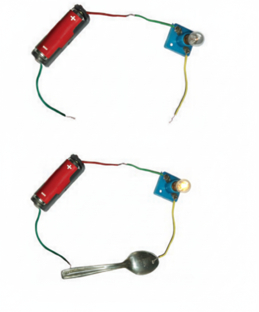
Table 3.3: Identifying Conductors and Insulators
Observation and Conclusion:
This activity demonstrates the difference between conductors and insulators. Conductors permit the flow of electric current, causing the lamp to glow, whereas insulators block the current, so the lamp remains off.
Understanding Electricity, Circuits, and Their Components
Mastering the basics of electricity and circuit components is crucial for scoring well in Class 7 Science. This chapter makes concepts like cells, batteries, conductors, and insulators easy to grasp for every learner.
Comprehending how electric circuits work through practical activities helps students apply knowledge beyond the textbook. Recognizing the flow direction of current and understanding circuit symbols will give you an edge in exams.
Practice is key—revise exercise-based questions and perform hands-on circuit activities to build confidence. These steps will boost your clarity on the topic and enhance your exam performance in Science Class 7.
FAQs on NCERT Solutions For Class 7 Science Chapter 3 Electricity Circuits And Their Components - 2026-27
1. What are the main components of an electric circuit covered in Class 7 Science Chapter 3?
The main components of an electric circuit are essential for understanding how electricity flows. In Class 7 Science Chapter 3: Electricity: Circuits and their Components, the key components include:
- Cells (batteries): Provide the electric current.
- Switches: Control the flow of current in the circuit (on/off).
- Connecting wires: Allow current to flow between components.
- Bulbs/Buzzers: Indicate when the circuit is complete by glowing or making sound.
2. How to draw circuit diagrams for Class 7 Science Chapter 3?
Drawing a correct circuit diagram helps you score full marks in CBSE Class 7 Science Chapter 3.
- Use standard symbols for cell, battery, switch, bulb, and wires.
- Draw straight lines for wires and neat, labelled symbols.
- Always close the circuit if you want the bulb to glow.
- Label each component clearly.
- Practice using the given textbook symbols for consistency.
3. Why is Chapter 3: Electricity: Circuits and their Components important for CBSE Class 7?
Chapter 3 is crucial because it introduces foundational electrical science concepts used in higher classes and real life.
- Teaches basics of current, circuits, and components.
- Improves diagram-drawing and labelling skills.
- Frequently appears in CBSE exams (~2–6 marks per set).
- Forms the base for advanced physics in later grades.
4. Are NCERT Solutions enough for scoring well in Class 7 Science exams?
NCERT Solutions are generally sufficient for scoring well in CBSE Class 7 Science exams, provided you:
- Write stepwise answers following textbook approach.
- Include diagrams and definitions as asked.
- Practice both intext and back exercise questions.
- Revise important questions and key definitions.
5. How do I structure long answers in Science Chapter 3 for better marks?
For long answers in Class 7 Science Chapter 3:
- Start with a definition or concept explanation.
- List steps/example with proper headings.
- Draw and label necessary diagrams neatly.
- Conclude with the final inference or summary.
- Underline keywords like circuit, switch, conductor, insulator.
6. Which questions are most likely to come from this chapter in school or CBSE exams?
The most common exam questions from Class 7 Science Chapter 3 include:
- Draw and label a simple electric circuit diagram.
- Define: conductor, insulator, switch, open and closed circuit.
- Differentiate between series and parallel circuits.
- Explain how a bulb glows in a circuit.
- Identify errors in a given circuit diagram.
7. Are diagrams or definitions mandatory in answers for Electricity: Circuits and their Components?
Yes, diagrams and definitions are often mandatory as per CBSE Science marking scheme:
- Include clear, labelled diagrams when the question demands.
- Definitions must be precise and in your own words.
- Use standard textbook terminology.
- For questions on parts/components, always support with labeled diagrams.
8. Where can I download the free PDF for Class 7 Science Chapter 3 NCERT solutions?
You can download free PDF solutions for Class 7 Science Chapter 3: Electricity: Circuits and their Components from trusted educational portals:
- Official NCERT websites or leading platforms providing NCERT-based solutions.
- Look for chapter-wise or exercise-wise downloads for 2026–27 syllabus.
- Ensure the PDF is reviewed by subject experts and aligns with latest CBSE marking schemes.
9. How to prepare and revise Science Chapter 3 quickly before exams?
To revise Class 7 Science Chapter 3 efficiently:
- Read key definitions and formulae.
- Practice 2–3 circuit diagrams from textbook exercises.
- Revise from quick notes or revision planners (1-day, 3-day plans).
- Attempt previous year/sample questions for pattern practice.
10. Do examiners award partial marks for correct steps even if the final answer is wrong?
Yes, in CBSE exams, partial marks are often awarded for writing correct steps, definitions, or diagrams even if the final answer is incorrect.
- Show all working steps for circuit diagrams or explanations.
- Use labeled diagrams—even a missed connection may earn step marks.
- Attempt every part of a multi-step answer for maximum scoring.
11. How do I learn and label circuit diagrams for Science Chapter 3?
Learning and labelling circuit diagrams is easy if you:
- Memorise standard symbols (cell, bulb, switch, wire).
- Practice neat diagrams as per textbook format.
- Label every part clearly—no skipping labels.
- Follow textbook conventions for CBSE Class 7 Science.
12. What are the key definitions and formulae from Class 7 Science Chapter 3?
Important definitions and concepts to remember:
- Electric circuit: A closed loop through which electric current can flow.
- Conductor & Insulator: Conductors allow electric current; insulators do not.
- Switch: Device to open/close the circuit.
- Current direction: Flows from positive (+) to negative (–) terminal of the cell.