


Ray Optics And Optical Instruments Class 12 Questions And Answers
Are you searching for NCERT solutions for class 12 physics chapter 9 pdf? Chapter 9 covers Ray Optics and Optical Instruments, which includes topics like reflection, refraction, lenses, and mirrors. Vedantu's NCERT Solutions provide clear answers to help you understand these important physics concepts easily.
 Table of Content
The solutions include:
- Step-by-step answers to all exercise questions on reflection and refraction
- Clear explanations of lens formula, mirror equation, and magnification
- Solutions covering optical instruments like microscopes and telescopes
- Complete class 12 physics chapter 9 ncert solutions in simple language
These solutions help you solve numerical problems and understand the theory behind ray optics. All answers are written in easy language so you can learn without any difficulty. Download the ncert solutions for class 12 physics chapter 9 pdf download for free and improve your physics preparation today!


Ans: We have,
Size of the candle, $h=2.5cm$
Let image size $=h'$
Object distance, $u=-27cm$
concave mirror’s curvature radius, $R=-36cm$
Focal length of the concave mirror, $f=\frac{R}{2}=-18cm$
Using mirror formula,
$\frac{1}{u}+\frac{1}{v}=\frac{1}{f}$
$\Rightarrow \frac{1}{v}=\frac{1}{f}-\frac{1}{u}$
Where, u is the object distance,
v is the image distance and
f is the focal length.
Now, we put given values,
$\Rightarrow \frac{1}{v}=\frac{1}{-18}-\frac{1}{-27}$
$\Rightarrow \frac{1}{v}=\frac{-3+2}{54}$
$\Rightarrow \frac{1}{v}=\frac{-1}{54}$
$\Rightarrow v=-54cm$
Therefore, the screen should be 54 cm away from the mirror to get a sharp image.
The formula for magnification of image is given by:
$m=\frac{h'}{h}=-\frac{v}{u}$
$\therefore h'=-\frac{v}{u}\times h$
$\Rightarrow h'=-\frac{-54}{-27}\times 2.5$
$\Rightarrow h'=-5cm$
The height of the image of the candle is \[5\text{ }cm\]. The negative sign shows that the image is inverted and real.
If the candle is moved nearer to the mirror, then the screen will have to be moved far from the mirror in order to get the image.
2. A \[\mathbf{4}.\mathbf{5}\text{ }\mathbf{cm}\] needle is placed \[\mathbf{12cm}\] away from a convex mirror of focal length \[\mathbf{15cm}\]. Give the location of the image and the magnification. Describe what happens as the needle is moved farther from the mirror.
Ans: Given that,
Height of the needle, \[{{h}_{1}}\text{ }=\text{ }4.5cm\]
Object distance, \[u\text{ }=\text{ }-12cm\]
Focal length of the convex mirror, \[f\text{ }=\text{ }15cm\]
Image distance \[=\text{ }v\]
Using mirror formula,
$\frac{1}{u}+\frac{1}{v}=\frac{1}{f}$
$\Rightarrow \frac{1}{v}=\frac{1}{f}-\frac{1}{u}$
Now, we put given values,
$\Rightarrow \frac{1}{v}=\frac{1}{15}-\frac{1}{-12}$
$\Rightarrow \frac{1}{v}=\frac{4+5}{60}$
$\Rightarrow \frac{1}{v}=\frac{9}{60}$
$\Rightarrow v=6.7cm$
Hence, the needle’s image is \[6.7\text{ }cm\] away from the mirror and it is on the mirror’s other side.
The formula for magnification of image is given by:
$m=\frac{{{h}_{2}}}{{{h}_{1}}}=-\frac{v}{u}$
$\therefore {{h}_{2}}=-\frac{v}{u}\times {{h}_{1}}$
$\Rightarrow {{h}_{2}}=-\frac{6.7}{-12}\times 4.5$
$\Rightarrow {{h}_{2}}=2.5cm$
The image’s height is 2.5cm. The positive sign shows that the image is virtual, erect, and diminished.
If the needle is moved away from the mirror, the image will also move farther from the mirror, and the size of the image will decrease gradually.
3. A tank is filled with water to a height of \[\mathbf{12}.\mathbf{5}\text{ }\mathbf{cm}\]. The apparent depth of a needle lying at the bottom of the tank is measured by a microscope to be \[\mathbf{9}.\mathbf{4cm}\]. What is the refractive index of water? If water is replaced by a liquid of refractive index \[\mathbf{1}.\mathbf{63}\] up to the same height, by what distance would the microscope have to be moved to focus on the needle again?
Ans: Given that,
Actual depth of the needle in water, \[{{h}_{1}}=12.5cm\]
Apparent depth of the needle in water, \[{{h}_{2}}=9.4cm\]
Refractive index of water $=\mu $
The formula for refractive index is given by:
$\mu =\frac{{{h}_{1}}}{{{h}_{2}}}$
Put the given values,
$\mu =\frac{12.5}{9.4}$
$\mu \approx 1.33$
Hence, the water’s refractive index is about \[1.33\].
When water is replaced by a liquid of refractive index, $\mu '=1.63$.
The actual depth of the needle will be the same, but it's apparent depth will vary.
Let \[y\] be the new apparent depth of the needle.
We will use the relation given below:
$\mu '=\frac{{{h}_{1}}}{y}$
$\therefore y=\frac{{{h}_{1}}}{\mu '}$
$\Rightarrow y=\frac{12.5}{1.63}$
$\Rightarrow y=7.67cm$
We get the new apparent depth of the needle to be \[7.67cm\]. It is less than ${{h}_{2}}$. Therefore, the microscope should be moved up to focus the needle again.
The distance by which the microscope would be moved up\[=\text{ }9.4\text{ }-\text{ }7.67\text{ }=\text{ }1.73cm\].
4. Figures (a) and (b) show the refraction of a ray in air incident at \[\mathbf{60}{}^\circ \] with the normal to a glass-air and water-air interface, respectively. Predict the angle of refraction in a glass when the angle of incidence in water is \[\mathbf{45}{}^\circ \] with the normal to a water-glass interface (figure (c)).
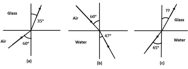
Ans: Given that,
For the glass -air interface,
Angle of incidence, \[i=\text{ }60{}^\circ \]
Angle of refraction, $r=35{}^\circ $
We can use Snell’s law,
$\mu _{g}^{a}=\frac{\sin i}{\sin r}$
$\Rightarrow \mu _{g}^{a}=\frac{\sin 60{}^\circ }{\sin 35{}^\circ }$
$\Rightarrow \mu _{g}^{a}=1.51$……(i)
For the air-water interface,
Angle of incidence, \[i=\text{ }60{}^\circ \]
Angle of refraction, $r=47{}^\circ $
We can use Snell’s law,
$\mu _{w}^{a}=\frac{\sin i}{\sin r}$
$\Rightarrow \mu _{w}^{a}=\frac{\sin 60{}^\circ }{\sin 47{}^\circ }$
$\Rightarrow \mu _{w}^{a}=1.184$……(ii)
Using (i) and (ii), the relative refractive index of glass with respect to water can be derived as:
$\mu _{g}^{w}=\frac{\mu _{g}^{a}}{\mu _{w}^{a}}$
$\Rightarrow \mu _{g}^{w}=\frac{1.51}{1.184}$
$\Rightarrow \mu _{g}^{w}=1.275$
For the glass - water interface,
Angle of incidence, \[i=\text{ 45}{}^\circ \]
Angle of refraction, $=r$
We can use Snell’s law,
$\mu _{g}^{w}=\frac{\sin i}{\sin r}$
$\Rightarrow 1.275=\frac{\sin 45{}^\circ }{\sin r}$
$\Rightarrow \sin r=0.5546$
$\Rightarrow r={{\sin }^{-1}}(0.5546)$
\[\Rightarrow r=38.68{}^\circ \]
Hence, the angle of refraction at the water – glass interface is $38.68{}^\circ $.
5. A small bulb is placed at the bottom of a tank containing water to a depth of \[\mathbf{80}\text{ }\mathbf{cm}\]. What is the area of the surface of water through which light from the bulb can emerge out? Refractive index of water is \[\mathbf{1}.\mathbf{33}.\](Consider the bulb to be a point source.)
Ans: Provided that,
Bulb’s actual depth in water, ${{d}_{1}}=80cm=0.8m$
Water’s refractive index, \[\mu =1.33\]
The following diagram represents the given setup:
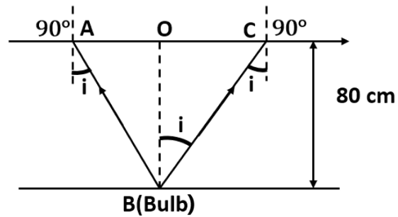
Where i is the Angle of incidence
r is the Angle of refraction, $r=90{}^\circ $
As the bulb acts as a point source, the emergent light would be considered as a circle of radius, $R=\frac{AC}{2}=AO=OB$
Snell’s law may be used as follows:
$\mu =\frac{\sin r}{\sin i}$
$\Rightarrow 1.33=\frac{\sin 90{}^\circ }{\sin i}$
$\Rightarrow \sin i=\frac{1}{1.33}$
$\Rightarrow i=48.75{}^\circ $
Considering the given diagram, we have the relation:
$\tan i=\frac{OC}{OB}=\frac{R}{{{d}_{1}}}$
$\Rightarrow R=\tan 48.75{}^\circ \times 0.8$
$\Rightarrow R=0.91m$
Area of the surface of water $=\pi {{R}^{2}}=\pi {{(0.91)}^{2}}=2.61{{m}^{2}}$
Clearly, the area of the water surface through which the light from the bulb could project is about $2.61{{m}^{2}}$.
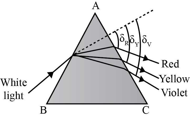
6. A prism is made of glass of unknown refractive index. A parallel beam of light is incident on a face of the prism. The angle of minimum deviation is measured to be \[\mathbf{40}{}^\circ \]. What is the refractive index of the material of the prism? The refracting angle of the prism is \[\mathbf{60}{}^\circ \]. If the prism is placed in water (refractive index \[\mathbf{1}.\mathbf{33}\]), predict the new angle of minimum deviation of a parallel beam of light.
Ans: The minimum deviation angle and the angle of the prism is as shown in the figure given below:
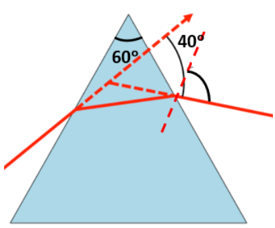
Angle of minimum deviation, ${{\delta }_{m}}=40{}^\circ $
Angle of the prism, $A=60{}^\circ $
Refractive index of water, $\mu =1.33$
Refractive index of the material of the prism $=\mu '$
The relation between angle of deviation with refractive index is given by:
$\mu '=\frac{\sin \left( \frac{A+{{\delta }_{m}}}{2} \right)}{\sin \left( \frac{A}{2} \right)}$
$\Rightarrow \mu '=\frac{\sin \left( \frac{60{}^\circ +40{}^\circ }{2} \right)}{\sin \left( \frac{60{}^\circ }{2} \right)}=\frac{\sin 50{}^\circ }{\sin 30{}^\circ }$
$\Rightarrow \mu '=1.532$
Hence, the refractive index of the prism is \[1.532\].
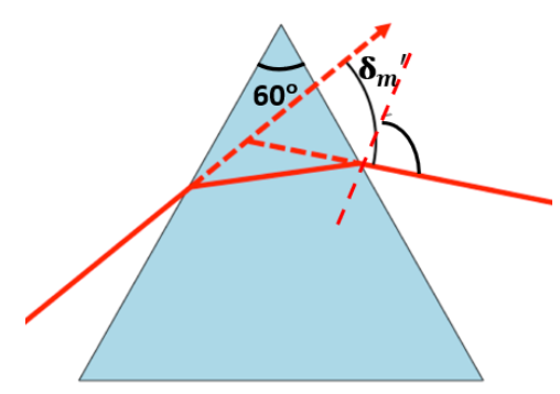
Since the prism is placed in water, let $\delta {{'}_{m}}$ be the new angle of minimum deviation for the same prism.
The below figure shows the angle of the prism and the unknown minimum deviation angle.
The refractive index of glass with respect to water is given by the relation:
$\mu _{g}^{w}=\frac{\mu '}{\mu }=\frac{\sin \left( \frac{A+\delta {{'}_{m}}}{2} \right)}{\sin \left( \frac{A}{2} \right)}$
$\Rightarrow \frac{\mu '}{\mu }\sin \left( \frac{A}{2} \right)=\sin \left( \frac{A+\delta {{'}_{m}}}{2} \right)$
$\Rightarrow \sin \left( \frac{A+\delta {{'}_{m}}}{2} \right)=\frac{1.532}{1.33}\sin \left( \frac{60{}^\circ }{2} \right)=0.5759$
$\Rightarrow \frac{A+\delta {{'}_{m}}}{2}={{\sin }^{-1}}\left( 0.5759 \right)=35.16{}^\circ $
$\Rightarrow 60{}^\circ +\delta {{'}_{m}}=70.32{}^\circ $
$\Rightarrow \delta {{'}_{m}}=10.32{}^\circ $
Hence, the new minimum angle of deviation is $10.32{}^\circ $.
7. Double-convex lenses are to be manufactured from a glass of refractive index \[\mathbf{1}.\mathbf{55}\], with both faces of the same radius of curvature. What is the radius of curvature required if the focal length is to be \[\mathbf{20}\text{ }\mathbf{cm}\]?
Ans: Given that,
Refractive index of glass, \[\mu =1.55\]
Focal length of the double-convex lens, \[f=20\text{ }cm\]
Radius of curvature of one face of the lens \[=\text{ }{{R}_{1}}\]
Radius of curvature of the other face of the lens \[=\text{ }{{R}_{2}}\]
Radius of curvature of the double-convex lens \[=\text{ }R\]
$\therefore {{R}_{1}}=R;\text{ }{{R}_{2}}=-R$
We can use this formula:
$\frac{1}{f}=\left( \mu -1 \right)\left[ \frac{1}{{{R}_{1}}}-\frac{1}{{{R}_{2}}} \right]$
$\Rightarrow \frac{1}{20}=\left( 1.55-1 \right)\left[ \frac{1}{R}+\frac{1}{R} \right]$
$\Rightarrow \frac{1}{20}=\left( 0.55 \right)\left[ \frac{2}{R} \right]$
$\therefore R=22cm$
Hence, the radius of curvature of the double-convex lens is $22cm$.
8. A beam of light converges at a point \[\mathbf{P}\]. Now a lens is placed in the path of the convergent beam \[\mathbf{12}\text{ }\mathbf{cm}\] from \[\mathbf{P}\]. At what point does the beam converge if the lens is
a) a convex lens of focal length \[\mathbf{20cm}\]?
Ans: Consider the given setup of a convex lens of focal length 20cm.
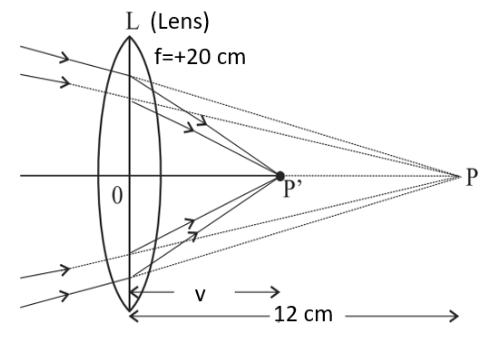
Object distance, \[u=+12\text{ }cm\]
Focal length of the convex lens, \[f=20\text{ }cm\]
Image distance \[=v\]
Using lens formula,
$\frac{1}{v}-\frac{1}{u}=\frac{1}{f}$
$\Rightarrow \frac{1}{v}-\frac{1}{12}=\frac{1}{20}$
$\Rightarrow \frac{1}{v}=\frac{1}{20}+\frac{1}{12}=\frac{8}{60}$
$\Rightarrow v=\frac{60}{8}=7.5cm$
Clearly, the image is formed \[7.5cm\] away from the lens, toward its right.
b) a concave lens of focal length \[\mathbf{16cm}\]?
Ans: Consider the given setup of a concave lens of focal length 16cm.
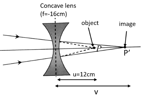
Focal length of the concave lens, $f=-16cm$
Image distance \[=\text{ }v\]
Using lens formula,
$\frac{1}{v}-\frac{1}{u}=\frac{1}{f}$
$\Rightarrow \frac{1}{v}=-\frac{1}{16}+\frac{1}{12}$
$\Rightarrow \frac{1}{v}=\frac{-3+4}{48}$
$\Rightarrow \frac{1}{v}=\frac{1}{48}$
$\therefore v=48cm$
Clearly, the image is formed \[48cm\] away from the lens, toward its right.
9. An object of size \[\mathbf{3}.\mathbf{0}\text{ }\mathbf{cm}\] is placed \[\mathbf{14}\text{ }\mathbf{cm}\] in front of a concave lens of focal length \[\mathbf{21cm}\]. Describe the image produced by the lens. What happens if the object is moved further away from the lens?
Ans: Given that,
Size of the object, \[{{h}_{1}}=3\text{ }cm\]
Object distance, \[u=-\text{ }14\text{ }cm\]
Focal length of the concave lens, \[f=-21\text{ }cm\]
Image distance \[=\text{ }v\]
Using lens formula,
$\frac{1}{v}-\frac{1}{u}=\frac{1}{f}$
$\Rightarrow \frac{1}{v}=-\frac{1}{21}-\frac{1}{14}$
$\Rightarrow \frac{1}{v}=\frac{-2-3}{42}$
$\Rightarrow \frac{1}{v}=\frac{-5}{42}$
$\therefore v=\frac{-42}{5}=-8.4cm$
Hence, the image is formed on the same side of the lens as the object, \[8.4\text{ }cm\] away from it. The negative sign indicates that the image is erect and virtual.
The formula for magnification of the image is given as:
$m=\frac{{{h}_{2}}}{{{h}_{1}}}=\frac{v}{u}$
$\therefore {{h}_{2}}=\frac{-8.4}{-14}\times 3=1.8cm$
$\Rightarrow {{h}_{2}}=1.8cm$
Hence, the height of the image is \[1.8\text{ }cm.\]
If the object is moved further away from the lens, then the virtual image will move towards the lens focus, but not beyond it. The image size will decrease with the increase in the distance of the object.
10. What is the focal length of a convex lens of focal length \[\mathbf{30}\text{ }\mathbf{cm}\] in contact with a concave lens of focal length \[\mathbf{20}\text{ }\mathbf{cm}\]? Is the system a converging or a diverging lens? Ignore thickness of the lenses.
Ans: Given that,
Focal length of the convex lens, \[{{f}_{1}}=30\text{ }cm\]
Focal length of the concave lens, \[{{f}_{2}}=-20\text{ }cm\]
Focal length of the system of lenses \[=\text{ }f\]
The equivalent focal length of two lenses system in contact is given by:
$\frac{1}{f}=\frac{1}{{{f}_{1}}}+\frac{1}{{{f}_{2}}}$
$\Rightarrow \frac{1}{f}=\frac{1}{30}-\frac{1}{20}=\frac{-1}{60}$
$\Rightarrow f=-60cm$
Hence, the focal length of the combination of lenses is \[60\text{ }cm\]. The negative sign shows that the system of lenses acts as a diverging lens.
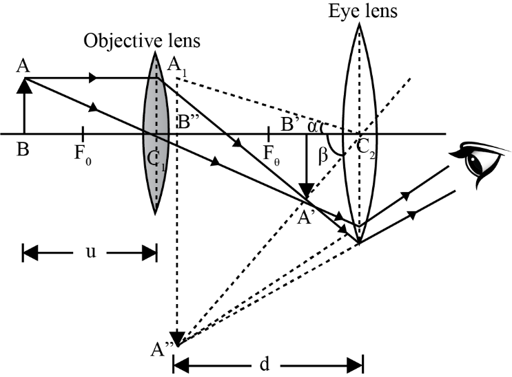
11. A compound microscope consists of an objective lens of focal length \[\mathbf{2}.\mathbf{0}\text{ }\mathbf{cm}\] and an eyepiece of focal length \[\mathbf{6}.\mathbf{25}\text{ }\mathbf{cm}\] separated by a distance of \[\mathbf{15}\text{ }\mathbf{cm}\]. How far from the objective should an object be placed in order to obtain the final image at:
a) the least distance of distinct vision (\[\mathbf{25}\text{ }\mathbf{cm}\])? What is the magnifying power of the microscope?
Ans: Given that,
Focal length of the objective lens, \[{{f}_{1}}=2.0\text{ }cm\]
Focal length of the eyepiece, \[{{f}_{2}}=\text{ }6.25\text{ }cm\]
Distance between the objective lens and the eyepiece, \[d\text{ }=\text{ }15\text{ }cm\]
Least distance of distinct vision, \[d'\text{ }=\text{ }25\text{ }cm\]
lmage distance for the eyepiece, \[{{v}_{2}}=-25\text{ }cm\]
Object distance for the eyepiece \[=\text{ }{{u}_{2}}\]
Using lens formula,
$\frac{1}{{{v}_{2}}}-\frac{1}{{{u}_{2}}}=\frac{1}{{{f}_{2}}}$
$\Rightarrow \frac{1}{{{u}_{2}}}=\frac{1}{{{v}_{2}}}-\frac{1}{{{f}_{2}}}$
$\Rightarrow \frac{1}{{{u}_{2}}}=\frac{1}{-25}-\frac{1}{6.25}$
$\Rightarrow \frac{1}{{{u}_{2}}}=\frac{-5}{25}$
$\Rightarrow {{u}_{2}}=-5cm$
The distance of image for the objective lens, ${{v}_{1}}=d+{{u}_{2}}=15-5=10cm$.
The distance of object for the objective lens $={{u}_{1}}$
Using lens formula,
$\frac{1}{{{v}_{1}}}-\frac{1}{{{u}_{1}}}=\frac{1}{{{f}_{1}}}$
$\Rightarrow \frac{1}{{{u}_{1}}}=\frac{1}{{{v}_{1}}}-\frac{1}{{{f}_{1}}}$
$\Rightarrow \frac{1}{{{u}_{1}}}=\frac{1}{10}-\frac{1}{2}$
$\Rightarrow \frac{1}{{{u}_{1}}}=\frac{-4}{10}$
$\Rightarrow {{u}_{1}}=-2.5cm$
Magnitude of the object distance, $|{{u}_{1}}|=2.5cm$.
The compound microscope’s magnifying power is given by the relation:
$m=\frac{{{v}_{1}}}{|{{u}_{1}}|}\left( 1+\frac{d'}{{{f}_{2}}} \right)$
$\Rightarrow m=\frac{10}{2.5}\left( 1+\frac{25}{6.25} \right)$
$\Rightarrow m=4(1+4)=20$
Hence, the magnifying power of the microscope is $20$.
b) at infinity? What is the magnifying power of the microscope?
Ans: Given that, the final image is formed at infinity.
The distance of image of the eyepiece, ${{v}_{2}}=\infty $
The distance of object of the eyepiece $={{u}_{2}}$
Using lens formula,
$\frac{1}{{{v}_{2}}}-\frac{1}{{{u}_{2}}}=\frac{1}{{{f}_{2}}}$
$\Rightarrow \frac{1}{{{u}_{2}}}=\frac{1}{{{v}_{2}}}-\frac{1}{{{f}_{2}}}$
$\Rightarrow \frac{1}{{{u}_{2}}}=\frac{1}{\infty }-\frac{1}{6.25}$
$\Rightarrow {{u}_{2}}=-6.25cm$
The distance of image for the objective lens, ${{v}_{1}}=d+{{u}_{2}}=15-6.25=8.75cm$.
The distance of object for the objective lens $={{u}_{1}}$
Using lens formula,
$\frac{1}{{{v}_{1}}}-\frac{1}{{{u}_{1}}}=\frac{1}{{{f}_{1}}}$
$\Rightarrow \frac{1}{{{u}_{1}}}=\frac{1}{{{v}_{1}}}-\frac{1}{{{f}_{1}}}$
$\Rightarrow \frac{1}{{{u}_{1}}}=\frac{1}{8.75}-\frac{1}{2}$
$\Rightarrow {{u}_{1}}=-2.59cm$
Magnitude of the object distance, $|{{u}_{1}}|=2.59cm$.
The compound microscope’s magnifying power is given by the relation:
$m=\frac{{{v}_{1}}}{|{{u}_{1}}|}\left( \frac{d'}{|{{u}_{2}}|} \right)$
$\Rightarrow m=\frac{8.75}{2.59}\left( \frac{25}{6.25} \right)$
$\Rightarrow m=13.51$
Hence, the magnifying power of the microscope is $13.51$.
12. A person with a normal near point (\[\mathbf{25}\text{ }\mathbf{cm}\]) using a compound microscope with objective of focal length \[\mathbf{8}.\mathbf{0}\text{ }\mathbf{mm}\] and an eyepiece of focal length \[\mathbf{2}.\mathbf{5}\text{ }\mathbf{cm}\] can bring an object placed at \[\mathbf{9}.\mathbf{0}\text{ }\mathbf{mm}\] from the objective in sharp focus. What is the separation between the two lenses? Calculate the magnifying power of the microscope.
Ans: Given that,
Focal length of the objective lens, \[{{f}_{o}}=8\text{ }mm=0.8\text{ }cm\]
Focal length of the eyepiece, \[{{f}_{e}}=2.5\text{ }cm\]
The distance of the object for the Objective lens, \[{{u}_{o}}=-9.0\text{ }mm=-0.9\text{ }cm\]
Least distance of distant vision, \[d=25\text{ }cm\]
Image distance for the eyepiece, \[{{v}_{e}}=-d=-25\text{ }cm\]
Object distance for the eyepiece, ${{u}_{e}}$
Using lens formula,
$\frac{1}{{{v}_{e}}}-\frac{1}{{{u}_{e}}}=\frac{1}{{{f}_{e}}}$
$\Rightarrow \frac{1}{{{u}_{e}}}=\frac{1}{{{v}_{e}}}-\frac{1}{{{f}_{e}}}$
$\Rightarrow \frac{1}{{{u}_{e}}}=\frac{1}{-25}-\frac{1}{2.5}$
$\Rightarrow \frac{1}{{{u}_{e}}}=\frac{-11}{25}$
$\Rightarrow {{u}_{e}}=-2.27cm$
Using lens formula, we can obtain image distance for the objective lens,${{v}_{o}}$, is given by:
$\frac{1}{{{v}_{o}}}-\frac{1}{{{u}_{o}}}=\frac{1}{{{f}_{o}}}$
$\Rightarrow \frac{1}{{{v}_{o}}}=\frac{1}{{{u}_{o}}}+\frac{1}{{{f}_{o}}}$
$\Rightarrow \frac{1}{{{v}_{o}}}=\frac{1}{0.8}-\frac{1}{0.9}$
$\Rightarrow \frac{1}{{{v}_{o}}}=\frac{0.1}{0.72}$
$\Rightarrow {{v}_{o}}=7.2cm$
The distance between the objective lens and the eyepiece, $|{{u}_{e}}|+{{v}_{o}}=2.27+7.2=9.47cm$
The microscope’s magnifying power is given by the relation:
$m=\frac{{{v}_{o}}}{|{{u}_{o}}|}\left( 1+\frac{d}{{{f}_{e}}} \right)$
$\Rightarrow m=\frac{7.2}{0.9}\left( 1+\frac{25}{2.5} \right)$
$\Rightarrow m=8(1+10)=88$
Hence, the magnifying power of the microscope is $88$.
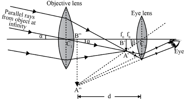
13. A small telescope has an objective lens of focal length \[\mathbf{144}\text{ }\mathbf{cm}\] and an eyepiece of focal length \[\mathbf{6}.\mathbf{0}\text{ }\mathbf{cm}\]. What is the magnifying power of the telescope? What is the separation between the objective and the eyepiece?
Ans: Given that,
Focal length of the objective lens, \[{{f}_{o}}=144\text{ }cm\]
Focal length of the eyepiece, \[{{f}_{e}}=6.0\text{ }cm\]
The telescope’s magnifying power is given by:
$m=\frac{{{f}_{o}}}{{{f}_{e}}}$
$\Rightarrow m=\frac{144}{6}$
$\Rightarrow m=24$
The separation between the objective lens and the eyepiece is given by:
$x={{f}_{o}}+{{f}_{e}}$
$\Rightarrow x=144+6=150cm$
Hence, the magnifying power of the telescope is \[24\] and the distance between the objective lens and the eyepieces is \[150cm\].
14.
a) A giant refracting telescope at an observatory has an objective lens of focal length \[\mathbf{15}\text{ }\mathbf{m}\]. If an eyepiece of focal length \[\mathbf{1}.\mathbf{0}\text{ }\mathbf{cm}\] is used, what is the angular magnification of the telescope?
Ans: Given that,
Focal length of the objective lens, \[{{f}_{o}}=15m=15\times 100=1500cm\]
Focal length of the eyepiece, \[{{f}_{e}}=\text{ }1.0\text{ }cm\]
The telescope’s angular magnification is given as:
$\alpha =\frac{{{f}_{o}}}{{{f}_{e}}}$
$\Rightarrow \alpha =\frac{1500}{1}=1500$
Hence, the refracting telescope’s angular magnification is \[1500.\]
b) If this telescope is used to view the moon, what is the diameter of the image of the moon formed by the objective lens? The diameter of the moon is \[\mathbf{3}.\mathbf{48}\text{ }\times \text{ }\mathbf{1}{{\mathbf{0}}^{6}}\text{ }\mathbf{m}\], and the radius of lunar orbit is \[\mathbf{3}.\mathbf{8}\text{ }\times \text{ }\mathbf{1}{{\mathbf{0}}^{8}}\text{ }\mathbf{m}\].
Ans: Given that,
Diameter of the moon, \[{{d}_{o}}=3.48\times {{10}^{6}}m\]
Radius of the lunar orbit, \[{{r}_{o}}=3.8\times {{10}^{8}}m\]
Let \[d'\] be the diameter of the moon image formed by the objective lens.
The angle subtended by the moon’s diameter is equal to the angle subtended by the image.
$\frac{{{d}_{o}}}{{{r}_{o}}}=\frac{d'}{{{f}_{o}}}$
\[\Rightarrow \frac{3.48\times {{10}^{6}}}{3.8\times {{10}^{8}}}=\frac{d'}{15}\]
$\Rightarrow d'=13.74\times {{10}^{-2}}m=13.74cm$
Hence, the diameter of the moon’s image formed by the objective lens is \[13.74\text{ }cm\].
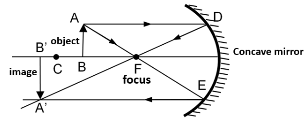
15. Use the mirror equation to deduce that:
a) an object placed between \[\mathbf{f}\] and \[~\mathbf{2f}\] of a concave mirror produces a real image beyond \[\mathbf{2f}\].
Ans: For a concave mirror, $f<0$.
When the object is placed on the left side of the mirror, then $u<0$.
Using mirror formula,
$\frac{1}{u}+\frac{1}{v}=\frac{1}{f}$
$\Rightarrow \frac{1}{v}=\frac{1}{f}-\frac{1}{u}$……(1)
If the object placed between $f$ and $2f$ $i.e.,2f<u<f$:
$\Rightarrow \frac{1}{2f}>\frac{1}{u}>\frac{1}{f}$
$\Rightarrow -\frac{1}{2f}<-\frac{1}{u}<-\frac{1}{f}$
$\Rightarrow \frac{1}{f}-\frac{1}{2f}<\frac{1}{f}-\frac{1}{u}<0$……(2)
Using equation (1), we get
$\Rightarrow \frac{1}{2f}<\frac{1}{v}<0$
Since $\frac{1}{v}$ is negative, $v$ is negative.
$\Rightarrow \frac{1}{2f}<\frac{1}{v}$
$\Rightarrow 2f>v$
$\Rightarrow -v>-2f$
Therefore, image will lie beyond $2f$.
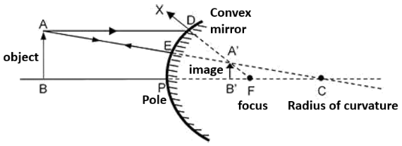
b) a convex mirror always produces a virtual image independent of the location of the object.
Ans: For a convex mirror, $f>0$.
When the object is placed on the left side of the mirror, then $u<0$.
Using mirror formula,
$\frac{1}{u}+\frac{1}{v}=\frac{1}{f}$
$\Rightarrow \frac{1}{v}=\frac{1}{f}-\frac{1}{u}$
Using equation (2), we get:
$\frac{1}{v}<0$
$\Rightarrow v>0$
Thus, the image is formed on the mirror’s backside.
Hence, a convex mirror always gives a virtual image, regardless of the object distance.
c) the virtual image produced by a convex mirror is always diminished in size and is located between the focus and the pole.
Ans: For a convex mirror, $f>0$.
Using mirror formula,
$\frac{1}{u}+\frac{1}{v}=\frac{1}{f}$
$\Rightarrow \frac{1}{v}=\frac{1}{f}-\frac{1}{u}$
But we have, $u<0$
$\therefore \frac{1}{v}>\frac{1}{f}$
$\Rightarrow v<f$
Hence, the image formed is diminished and is located between the focus and the pole.
d) An object placed between the pole and the focus of a concave mirror produces a virtual and enlarged image.
Ans: For a concave mirror, $f<0$.
When the object is placed on the left side of the mirror, then $u<0$.
The object is placed between the focus and the pole.
$\therefore f>u>0$
$\Rightarrow \frac{1}{f}<\frac{1}{u}<0$
$\Rightarrow \frac{1}{f}-\frac{1}{u}<0$
$\therefore \frac{1}{v}<0$
$\Rightarrow v>0$
The image is formed on the mirror’s right side. Hence, it is a virtual image.
For $u<0,v>0$
$\Rightarrow \frac{1}{u}>\frac{1}{v}$
$\Rightarrow v>u$
Magnification, $m=\frac{v}{u}>1$
Hence, the formed image is enlarged.
16. A small pin fixed on a tabletop is viewed from above from a distance of \[\mathbf{50}\text{ }\mathbf{cm}\]. By what distance would the pin appear to be raised if it is viewed from the same point through a \[\mathbf{15}\text{ }\mathbf{cm}\] thick glass slab held parallel to the table? Refractive index of glass \[\mathbf{1}.\mathbf{5}\]. Does the answer depend on the location of the slab?
Ans: According to the question,
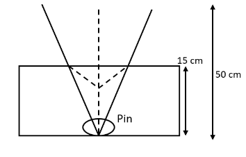
Actual depth of the pin, \[d=15\text{ }cm\]
Apparent depth of the pin \[=d'\]
Refractive index of glass, $\mu =1.5$
The refractive index of glass is equal to the ratio of actual depth to the apparent depth, that is,
$\mu =\frac{d}{d'}$
$\therefore d'=\frac{d}{\mu }$
$\Rightarrow d'=\frac{15}{1.5}=10cm$
The distance at which the pin appears to be raised $=d'-d=15-10=5cm$.
For a small incidence angle, this distance does not depend upon the slab location.
17.
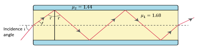
a) Figure shows a cross-section of a 'light pipe' made of a glass fibre of refractive index \[\mathbf{1}.\mathbf{68}\]. The outer covering of the pipe is made of a material of refractive index \[\mathbf{1}.\mathbf{44}\]. What is the range of the angles of the incident rays with the axis of the pipe for which total reflections inside the pipe take place, as shown in the figure?
Ans: Given that,
Refractive index of the glass fibre, ${{\mu }_{1}}=1.68$
Refractive index of the outer covering of the pipe, ${{\mu }_{2}}=1.44$
Angle of incidence \[=\text{ }i\]
Angle Of refraction \[=\text{ }r\]
Angle of incidence at the interface \[=\text{ }i'\]
The refractive index ($\mu $) of the inner core - outer core interface is given as:
$\mu =\frac{{{\mu }_{2}}}{{{\mu }_{1}}}=\frac{1}{\sin i'}$
\[\Rightarrow \sin i'=\frac{{{\mu }_{1}}}{{{\mu }_{2}}}\]
\[\Rightarrow \sin i'=\frac{1.44}{1.68}=0.8571\]
For the critical angle, total internal reflection (TIR) takes place only when $i>i'$.
That is, when $i>59{}^\circ $.
Maximum angle of reflection, ${{r}_{\max }}=90{}^\circ -i'=90{}^\circ -59{}^\circ =31{}^\circ $.
Let ${{i}_{\max }}$ be the maximum incidence angle.
The refractive index at the air – glass interface, ${{\mu }_{1}}=1.68$.
We can use the relation for the maximum angles of incidence and reflection as:
${{\mu }_{1}}=\frac{\sin {{i}_{\max }}}{\sin {{r}_{\max }}}$
\[\Rightarrow \sin {{i}_{\max }}={{\mu }_{1}}\times \sin {{r}_{\max }}\]
\[\Rightarrow \sin {{i}_{\max }}=1.68\times \sin 31{}^\circ \]
\[\Rightarrow \sin {{i}_{\max }}=0.8652\]
\[\Rightarrow {{i}_{\max }}\approx 60{}^\circ \]
Thus, all the ray’s incident at angles lying in the range $0<i<60{}^\circ $ will suffer total internal reflection.
b) What is the answer if there is no outer covering of the pipe?
Ans: If the outer covering of the pipe is not present, then:
Refractive index of the outer pipe $={{\mu }_{1}}$
Refractive index of air \[=\text{ }1\]
For the angle of incidence \[i\text{ =}90{}^\circ \], we can use Snell’s law at the air – pipe interface as
${{\mu }_{2}}=\frac{\sin i}{\sin r}$
$\Rightarrow 1.68=\frac{\sin 90{}^\circ }{\sin r}$
$\Rightarrow \sin r=\frac{1}{1.68}$
$\Rightarrow r=36.5{}^\circ $
$\therefore i'=90{}^\circ -36.5{}^\circ =53.5{}^\circ $
Since, $i'>r$, all incident rays will suffer total internal reflection.
18. The image of a small electric bulb fixed on the wall of a room is to be obtained on the opposite wall \[\mathbf{3}\text{ }\mathbf{m}\] away by means of a large convex lens. What is the maximum possible focal length of the lens required for the purpose?
Ans: Given that,
Distance between the object and the image, \[d=3\text{ }m\]
Maximum focal length of the convex lens $={{f}_{\max }}$
The maximum focal length is given by for real image:
${{f}_{\max }}=\frac{d}{4}$
$\Rightarrow {{f}_{\max }}=\frac{3}{4}=0.75m$
Hence, for the required purpose, the maximum possible focal length of the convex lens is \[0.75\text{ }m.\]
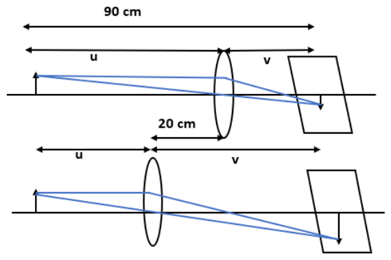
19. A screen is placed \[\mathbf{90}\text{ }\mathbf{cm}\] from an object. The image of the object on the screen is formed by a convex lens at two different locations separated by \[\mathbf{20}\text{ }\mathbf{cm}\]. Determine the focal length of the lens.
Ans: The figure shows the given arrangement of convex lens.
Here,
Distance between the image (screen) and the object, \[D\text{ }=\text{ }90\text{ }cm\].
Distance between two locations of the convex lens, \[d\text{ }=\text{ }20\text{ }cm\].
Focal length of the lens \[=\text{ }f\]
Focal length is related to \[d\] and \[D\] by:
$f=\frac{{{D}^{2}}-{{d}^{2}}}{4D}$
$\Rightarrow f=\frac{{{90}^{2}}-{{20}^{2}}}{4\times 90}=\frac{770}{36}$
$\Rightarrow f=21.39cm$
Clearly, the focal length of the convex lens is \[21.39cm.\]
20.
a) Determine the 'effective focal length' of the combination of the two lenses in Exercise 9.10, if they are placed \[\mathbf{8}.\mathbf{0}\text{ }\mathbf{cm}\] apart with their principal axes coincident. Does the answer depend on which side of the combination a beam of parallel light is incident? Is the notion of effective focal length of this system useful at all?
Ans: Consider the diagram below which represents the combination of two lenses.
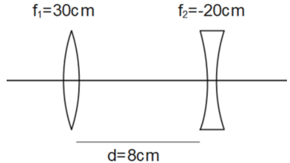
Here,
Focal length of the convex lens, \[{{f}_{1}}=30\text{ }cm\]
Focal length of the concave lens, \[{{f}_{2}}=-20\text{ }cm\]
Distance between the two lenses, \[d=8.0\text{ }cm\]
First, consider the case when the parallel beam of light falls on the convex lens.
Using lens formula,
$\frac{1}{{{v}_{1}}}-\frac{1}{{{u}_{1}}}=\frac{1}{{{f}_{1}}}$
Where, object distance, ${{u}_{1}}=\infty $
Image distance $={{v}_{1}}$
$\Rightarrow \frac{1}{{{v}_{1}}}=\frac{1}{30}-\frac{1}{\infty }=\frac{1}{30}$
$\Rightarrow {{v}_{1}}=30cm$
The image will serve as a virtual object for the concave lens.
Using lens formula,
$\frac{1}{{{v}_{2}}}-\frac{1}{{{u}_{2}}}=\frac{1}{{{f}_{2}}}$
Where, object distance $={{u}_{2}}$.
${{u}_{2}}=30-8=22cm$
Image distance $={{v}_{2}}$.
$\Rightarrow \frac{1}{{{v}_{2}}}=\frac{1}{22}-\frac{1}{20}=\frac{-1}{220}$
$\Rightarrow {{v}_{2}}=-220cm$
The parallel incident beam seems to diverge from a point, that is, $220-\frac{d}{2}=220-4=216cm$ from the centre of the combination of the two lenses.
Secondly, when the parallel beam of light falls, from the left, on the concave lens;
Using lens formula,
$\frac{1}{{{v}_{2}}}-\frac{1}{{{u}_{2}}}=\frac{1}{{{f}_{2}}}$
Where, object distance, ${{u}_{2}}=-\infty $.
Image distance $={{v}_{2}}$.
$\Rightarrow \frac{1}{{{v}_{2}}}=\frac{1}{-20}-\frac{1}{\infty }=\frac{1}{-20}$
$\Rightarrow {{v}_{2}}=-20cm$
The image will serve as a real object for the convex lens.
Using lens formula,
$\frac{1}{{{v}_{1}}}-\frac{1}{{{u}_{1}}}=\frac{1}{{{f}_{1}}}$
Where, object distance, $={{u}_{1}}$.
${{u}_{1}}=-(20+8)=-28cm$.
Image distance $={{v}_{1}}$.
$\Rightarrow \frac{1}{{{v}_{1}}}=\frac{1}{30}+\frac{1}{-28}=\frac{-1}{420}$
$\Rightarrow {{v}_{1}}=-420cm$
Hence, the parallel incident beam seems to diverge from a point, that is $=420-4=416cm$ from the left of the centre of the combination of the two lenses.
Thus, the answer does depend on the combination side at which the parallel beam of light is incident. The notion of effective focal length does not appear to be useful for this combination.
b) An object \[\mathbf{1}.\mathbf{5}\text{ }\mathbf{cm}\] in size is placed on the side of the convex lens in the arrangement (a) above. The distance between the object and the convex lens is \[\mathbf{40cm}\]. Determine the magnification produced by the two-lens system, and the size of the image.
Ans: Consider the given diagram of the previous arrangement as follows:
Here, it is said that,
Height of the image, \[{{h}_{1}}=1.5\text{ }cm\]
Object distance from the side of the convex lens, ${{u}_{1}}=-40cm$
$|{{u}_{1}}|=40cm$
Using lens formula,
$\frac{1}{{{v}_{1}}}-\frac{1}{{{u}_{1}}}=\frac{1}{{{f}_{1}}}$
$\Rightarrow \frac{1}{{{v}_{1}}}=\frac{1}{30}+\frac{1}{-40}=\frac{1}{120}$
$\Rightarrow {{v}_{1}}=120cm$
Magnification, $m=\frac{{{v}_{1}}}{|{{u}_{1}}|}$
$\Rightarrow m=\frac{120}{40}=3$
Hence, the magnification due to the convex lens is \[3\].
The image made by the convex lens acts as an object for the concave lens.
Using lens formula,
$\frac{1}{{{v}_{2}}}-\frac{1}{{{u}_{2}}}=\frac{1}{{{f}_{2}}}$
Where, object distance $={{u}_{2}}$.
${{u}_{2}}=120-8=112cm$.
Image distance $={{v}_{2}}$.
$\Rightarrow \frac{1}{{{v}_{2}}}=\frac{1}{-20}+\frac{1}{112}=\frac{-92}{2240}$
$\Rightarrow {{v}_{2}}=-\frac{2240}{92}cm$
Magnification, $m'=\frac{|{{v}_{1}}|}{|{{u}_{1}}|}$
$\Rightarrow m'=\frac{2240}{92}\times \frac{1}{112}=\frac{20}{92}$
Hence, the magnification due to the concave lens is $\frac{20}{92}$.
The magnification due to the combination of the two lenses is calculated as:
$m\times m'=3\times \frac{20}{92}=0.652$
Thus,
$\frac{{{h}_{2}}}{{{h}_{1}}}=0.652$
$\Rightarrow {{h}_{2}}=0.652\times 1.5=0.98cm$
Clearly, the height of the image is \[0.98cm\].
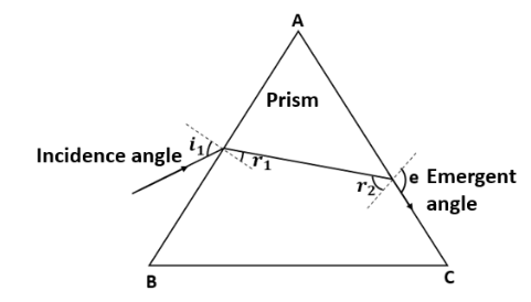
21. At what angle should a ray of light be incident on the face of a prism of refracting angle \[\mathbf{60}{}^\circ \] so that it just suffers total internal reflection at the other face? The refractive index of the material of the prism is \[\mathbf{1}.\mathbf{524}\].
Ans: Consider the given figure below:
Angle of prism, $A=60{}^\circ $
\[{{i}_{1}}\] is the incidence angle.
${{r}_{1}}$ is the refracted angle.
${{r}_{2}}$ is the angle of incidence at the face AC.
$e$is the emergent angle, $e=90{}^\circ $.
Using Snell’s law,
$\mu =\frac{\sin e}{\sin {{r}_{2}}}$
$\Rightarrow 1.524=\frac{\sin 90{}^\circ }{\sin {{r}_{2}}}$
$\Rightarrow \sin {{r}_{2}}=0.6562$
$\Rightarrow {{r}_{2}}\approx 41{}^\circ $
For refraction through prism, angle $A={{r}_{1}}+{{r}_{2}}$.
We get,
${{r}_{1}}=A-{{r}_{2}}=60{}^\circ -41{}^\circ $
$\therefore {{r}_{1}}=19{}^\circ $
Using Snell’s law,
$\mu =\frac{\sin {{i}_{1}}}{\sin {{r}_{1}}}$
$\Rightarrow 1.524=\frac{\sin {{i}_{1}}}{\sin 19{}^\circ }$
$\Rightarrow \sin {{i}_{1}}=0.496$
$\Rightarrow {{i}_{1}}=29.75{}^\circ $
Hence, the incidence angle is $29.75{}^\circ $.
22. A card sheet divided into squares each of size \[\mathbf{1}\text{ }\mathbf{m}{{\mathbf{m}}^{2}}\] is being viewed at a distance of \[\mathbf{9}\text{ }\mathbf{cm}\] through a magnifying glass (a converging lens of focal length \[\mathbf{9}\text{ }\mathbf{cm}\]) held close to the eye.
a) What is the magnification produced by the lens? How much is the area of each square in the virtual image?
Ans: Given that,
Area of each square, $A=\mathbf{1}\text{ }\mathbf{m}{{\mathbf{m}}^{2}}$
Object distance, $u=-9cm$
Focal length, $f=10cm$
Using lens formula,
$\frac{1}{f}=\frac{1}{v}-\frac{1}{u}$
$\Rightarrow \frac{1}{10}=\frac{1}{v}-\frac{1}{-9}$
$\Rightarrow v=-90cm$
Magnification, $m=\frac{v}{u}$
$\Rightarrow m=\frac{-90}{-10}=9$
Area of each square in the virtual image \[={{10}^{2}}A\]
\[{{10}^{2}}\times 1=100m{{m}^{2}}=1c{{m}^{2}}\]
b) What is the angular magnification (magnifying power) of the lens?
Ans: Magnifying power of the lens, $m=\frac{d}{|u|}$
$\Rightarrow m=\frac{25}{9}=2.8$
c) Is the magnification in (a) equal to the magnifying power in (b)? Explain.
Ans: The magnification in (a) is not the same as the magnifying power in (b).
The magnification magnitude is $\left| \frac{v}{u} \right|$ and the magnifying power is $\frac{d}{|u|}$.
The two quantities will be same when the image is formed at the close point \[\left( 25cm \right)\].
23.
a) At what distance should the lens be held from the figure in Exercise 9.29 in order to view the squares distinctly with the maximum possible magnifying power?
Ans: The maximum possible magnification got when the image is made at the near point \[\left( d\text{ }=\text{ }25\text{ }cm \right).\]
Image distance, \[v=-d=-25\text{ }cm\]
Focal length, \[f\text{ }=\text{ }10\text{ }cm\]
Object distance \[=\text{ }u\]
Using lens formula,
$\frac{1}{f}=\frac{1}{v}-\frac{1}{u}$
$\Rightarrow \frac{1}{10}=\frac{1}{-25}-\frac{1}{u}$
$\Rightarrow u=\frac{-50}{7}cm=-7.14cm$
Hence, to view the squares distinctly, the lens should be kept \[7.14cm\] away from them.
b) What is the magnification in this case?
Ans: Magnification, $m=\left| \frac{v}{u} \right|$
$\Rightarrow m=\frac{25}{\frac{50}{7}}=3.5$
c) Is the magnification equal to the magnifying power in this case? Explain.
Ans: Magnifying power, $m'=\frac{d}{u}$
$\Rightarrow m'=\frac{25}{\frac{50}{7}}=3.5=m$
Since the image is made at the near point \[\left( \mathbf{25}\text{ }\mathbf{cm} \right)\], the magnifying power is equal to the magnification magnitude.
24. What should be the distance between the Object in Exercise 9.30 and the magnifying glass if the virtual image of each square in the figure is to have an area of \[\mathbf{6}.\mathbf{25}\text{ }\mathbf{m}{{\mathbf{m}}^{2}}\]. Would you be able to see the squares distinctly with your eyes very close to the magnifier?
Ans: Given that,
Area of the virtual image of each square, \[A=6.25\text{ }m{{m}^{2}}\]
Area of each square, \[{{A}_{o}}=1\text{ }m{{m}^{2}}\]
Hence, the linear magnification is given by:
$m=\sqrt{\frac{A}{{{A}_{o}}}}$
$m=\sqrt{\frac{6.25}{1}}=2.5$
But,
$m=\frac{v}{u}$
$\Rightarrow v=2.5u$
Focal length of the magnifying glass, \[f=10cm\]
Using lens formula,
$\frac{1}{f}=\frac{1}{v}-\frac{1}{u}$
$\Rightarrow \frac{1}{10}=\frac{1}{2.5u}-\frac{1}{u}$
$\Rightarrow u=\frac{-1.5\times 10}{2.5}cm=-6cm$
And,
$v=2.5u$
$\Rightarrow v=2.5\times -6=-15cm$
The virtual image is made at a distance of \[15\text{ }cm\], which is less than the near point of a normal eye. Hence it cannot be visible by the eye distinctly.
25.
a) The angle subtended at the eye by an object is equal to the angle subtended at the eye by the virtual image produced by a magnifying glass. In what sense then does a magnifying glass provide angular magnification?
Ans: Though the image size is larger than the object, the angular size of the image is equivalent to the angular size of the object.
A magnifying glass supports one seeing the objects closer than the least distance of distinct vision. A closer object produces a larger angular size.
A magnifying glass gives angular magnification. Without magnification, the object cannot be located closer to the eye. With magnification, the object can be set much closer to the eye.
b) In viewing through a magnifying glass, one usually positions one's eyes very close to the lens. Does angular magnification change if the eye is moved back?
Ans: Yes, the angular magnification varies.
When the length between the eye and a magnifying glass rises, the angular magnification reduces slightly because the subtended angle at the eye is imperceptibly less than the lenses.
Image distance does not have any impact on angular magnification.
c) Magnifying power of a simple microscope is inversely proportional to the focal length of the lens. What then stops us from using a convex lens of smaller and smaller focal length and achieving greater and greater magnifying power?
Ans: The convex lens's focal length cannot be reduced by a more significant amount.
This is because making lenses having tiny focal lengths is not easy.
Spherical and chromatic aberrations are created by a convex lens having a petite focal length.
d) Why must both the objective and the eyepiece of a compound microscope have short focal lengths?
Ans: The angular magnification produced by the compound microscope’s eyepiece is:
$\left[ \left( \frac{25}{{{f}_{e}}} \right)+1 \right]$
Where, ${{f}_{e}}$ is the eyepiece's focal length.
It can be seen that if ${{f}_{e}}$ is small, then angular magnification of the eyepiece will be great.
The angular magnification of the compound microscope’s objective lens is given as $\frac{{{f}_{o}}}{{{u}_{o}}}$.
${{u}_{o}}$: Object distance for the objective lens
${{f}_{o}}$: Objective's focal length
The magnification is large when ${{u}_{o}}>{{f}_{o}}$.
In the case of a microscope, the object is placed close to the objective lens. Hence, the object distance is tiny.
Since ${{u}_{o}}$ is small, ${{f}_{o}}$ will be smaller. Therefore, ${{f}_{e}}$ and ${{f}_{o}}$ are both small for the given condition.
e) When viewing through a compound microscope, our eyes should be positioned not on the eyepiece but a short distance away from it for best viewing. Why? How much should be that short distance between the eye and eyepiece?
Ans: We cannot collect much-refracted light when we put our eyes too close to the compound microscope's eyepiece.
As a result, the field view reduces substantially. Hence, the image's clarity gets blurred.
The best view of the eye for seeing through a compound microscope is at the eye-ring connected to the eyepiece. The exact location of the eye depends on the separation between the objective lens and the eyepiece.
26. An angular magnification (magnifying power) of \[\mathbf{30X}\] is desired using an objective of focal length \[\mathbf{1}.\mathbf{25}\text{ }\mathbf{cm}\] and an eyepiece of focal length \[\mathbf{5}\text{ }\mathbf{cm}.\] How will you set up the compound microscope?
Ans: Given that,
Focal length of the objective lens, ${{f}_{o}}=1.25cm$
Focal length of the eyepiece, \[{{f}_{e}}=5\text{ }cm\]
Least distance of distinct vision, \[d\text{ }=\text{ }25\text{ }cm\]
Angular magnification of the compound microscope \[=\text{ }30X\]
Total magnifying power of the compound microscope, \[m\text{ = }30\]
The eyepiece’s angular magnification is given by:
${{m}_{e}}=1+\frac{d}{{{f}_{e}}}$
\[\Rightarrow {{m}_{e}}=1+\frac{25}{5}\]
$\Rightarrow {{m}_{e}}=6$
The objective lens angular magnification is given by:
$m={{m}_{o}}{{m}_{e}}$
$\Rightarrow {{m}_{o}}=\frac{m}{{{m}_{e}}}$
\[\Rightarrow {{m}_{o}}=\frac{30}{6}=5\]
We have,
${{m}_{o}}=\frac{{{v}_{o}}}{-{{u}_{o}}}$
\[\Rightarrow 5=\frac{{{v}_{o}}}{-{{u}_{o}}}\]
\[\Rightarrow {{v}_{o}}=-5{{u}_{o}}\]……(1)
Using lens formula,
$\frac{1}{{{f}_{o}}}=\frac{1}{{{v}_{o}}}-\frac{1}{{{u}_{o}}}$
$\Rightarrow \frac{1}{1.25}=\frac{1}{-5{{u}_{o}}}-\frac{1}{{{u}_{o}}}$
$\Rightarrow {{u}_{o}}=-1.5cm$
And, \[{{v}_{o}}=-5{{u}_{o}}=-5\times -1.5=7.5cm\]
The object should be placed \[1.5cm\] away from the objective lens to get the desired magnification.
Using lens formula,
$\frac{1}{{{f}_{e}}}=\frac{1}{{{v}_{e}}}-\frac{1}{{{u}_{e}}}$
Where, ${{v}_{e}}=-d=-25cm$
$\Rightarrow \frac{1}{5}=\frac{1}{-25}-\frac{1}{{{u}_{e}}}$
$\Rightarrow {{u}_{e}}=-4.17cm$
Separation between the eyepiece and the objective lens $=|{{u}_{e}}|+|{{v}_{o}}|$
$|{{u}_{e}}|+|{{v}_{o}}|=4.17+7.5=11.67cm$
Therefore, the separation between the eyepiece and the objective lens should be \[11.67cm.\]
27. A small telescope has an objective lens of focal length \[\mathbf{140}\text{ }\mathbf{cm}\] and an eyepiece of focal length \[\mathbf{5}.\mathbf{0}\text{ }\mathbf{cm}\]. What is the magnifying power of the telescope for viewing distant objects when
a) the telescope is in normal adjustment (i.e., when the final image is at infinity)?
Ans: Given that,
Focal length of the objective lens, ${{f}_{o}}=140cm$
Focal length of the eyepiece, \[{{f}_{e}}=5\text{ }cm\]
Least distance of distinct vision, \[d\text{ }=\text{ }25\text{ }cm\]
When the telescope is in normal adjustment, formula for magnifying power is given by:
$m=\frac{{{f}_{o}}}{{{f}_{e}}}$
$\Rightarrow m=\frac{140}{5}=28$
b) the final image is formed at the least distance of distinct vision \[\left( \mathbf{25}\text{ }\mathbf{cm} \right)\]?
Ans: When the final image is formed at \[d\], the formula for magnifying power of telescope is given by:
$m=\frac{{{f}_{o}}}{{{f}_{e}}}\left( 1+\frac{{{f}_{e}}}{d} \right)$
$\Rightarrow m=\frac{140}{5}\left( 1+\frac{5}{25} \right)=28[1+0.2]$
\[\Rightarrow m=33.6\]
28.
a) For the telescope described in Exercise 9.34 (a), what is the separation between the objective lens and the eyepiece?
Ans: Given that,
Focal length of the objective lens, \[{{f}_{o}}=140\text{ }cm\]
Focal length of the eyepiece, \[{{f}_{e}}=5\text{ }cm\]
The separation between the objective lens and the eyepiece in normal adjustment $={{f}_{o}}+{{f}_{e}}=(140+5)\text{ }cm=145cm$
b) If this telescope is used to view a \[\mathbf{100}\text{ }\mathbf{m}\] tall tower \[\mathbf{3}\text{ }\mathbf{km}\] away, what is the height of the image of the tower formed by the objective lens?
Ans: Given that,
Height of the tower, \[{{h}_{1}}=100\text{ }m\]
Distance of the tower from the telescope, \[u\text{ }=\text{ }3\text{ }km\text{ }=\text{ }3000\text{ }m\]
The angle subtended by the tower at the telescope is given as:
$\theta =\frac{{{h}_{1}}}{u}$
$\Rightarrow \theta =\frac{100}{3000}=\frac{1}{30}rad$
The angle subtended by the image made by the objective lens is given by:
$\theta =\frac{{{h}_{2}}}{{{f}_{o}}}$
$\Rightarrow \frac{1}{30}=\frac{{{h}_{2}}}{140}$
$\therefore {{h}_{2}}=4.7cm$
Therefore, the objective lens forms a \[4.7cm\] tall image of the tower.
c) What is the height of the final image of the tower if it is formed at \[\mathbf{25}\text{ }\mathbf{cm}\]?
Ans: Given that,
Image is formed at a distance, \[d\text{ }=\text{ }25cm\]
The eyepiece’s magnification is given by:
$m=1+\frac{d}{{{f}_{e}}}$
\[\Rightarrow m=1+\frac{25}{5}\]
$\Rightarrow m=6$
Height of the final image, $=m\times {{h}_{2}}=6\times 4.7=28.2cm$
Hence, the final image’ height of the tower is \[28.2cm\].
29. A Cassegrain telescope uses two mirrors as shown in figure. Such a telescope is built with the mirrors \[\mathbf{20}\text{ }\mathbf{mm}\] apart. If the radius of curvature of the large mirror is \[\mathbf{220}\text{ }\mathbf{mm}\] and these all mirror is \[\mathbf{140mm}\], where will the final image of an object at infinity be?
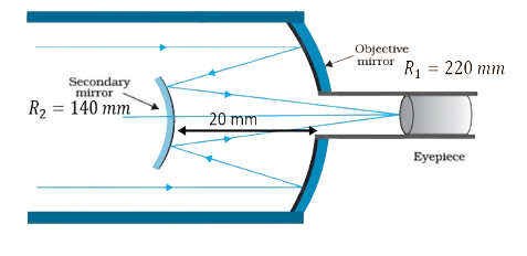
Ans: A Cassegrain telescope contains two mirrors, one is an objective mirror and the second one is the secondary mirror. We need to find the distance of the final image from the secondary mirror.
Given: distance between the objective mirror and the secondary mirror, \[d=20mm\]
Radius of curvature of the objective mirror, \[{{R}_{1}}=220\text{ }mm\]
Hence, objective mirror’s focal length, ${{f}_{1}}=\frac{{{R}_{1}}}{2}=110mm$
Secondary mirror’s radius of curvature, \[{{R}_{2}}=140\text{ }mm\]
Secondary mirror’s focal length, ${{f}_{2}}=\frac{{{R}_{2}}}{2}=70mm$
The image of an object set at infinity, made by the objective mirror, will serve as a virtual object for the secondary mirror.
Hence, the secondary mirror’s virtual object distance, $u={{f}_{1}}-d$
$\Rightarrow u=110-20=90mm$
Using mirror formula,
$\frac{1}{u}+\frac{1}{v}=\frac{1}{{{f}_{2}}}$
$\Rightarrow \frac{1}{v}=\frac{1}{{{f}_{2}}}-\frac{1}{u}$
Now, we put given values,
$\Rightarrow \frac{1}{v}=\frac{1}{70}-\frac{1}{90}$
$\Rightarrow \frac{1}{v}=\frac{9-7}{630}$
$\Rightarrow \frac{1}{v}=\frac{2}{630}$
$\Rightarrow v=315mm$
Clearly, the final image will be made \[315\text{ }mm\] away from the secondary mirror.
30. Light incident normally on a plane mirror attached to a galvanometer coil retraces backwards as shown in figure. A current in the coil produces a deflection of \[\mathbf{3}.\mathbf{5}{}^\circ \] from the mirror. What is the displacement of the reflected spot of light on a screen placed \[\mathbf{1}.\mathbf{5}\text{ }\mathbf{m}\] away?

Ans: Angle of deflection, $\theta =\mathbf{3}.\mathbf{5}{}^\circ $
Screen distance from the mirror, \[D=1.5\text{ }m\]
The reflected rays will deflect by an amount twice the deflection angle, $2\theta =7{}^\circ $.
The displacement of the light’s reflected spot on the screen is given as:
$\tan 2\theta =\frac{d}{1.5}$
$\therefore d=1.5\times \tan 7{}^\circ =0.184m=18.4cm$
Hence, the displacement of the reflected spot of light is \[18.4\text{ }cm.\]
31. Figure shows an equiconvex lens (of refractive index \[\mathbf{1}.\mathbf{50}\]) in contact with a liquid layer on top of a plane mirror. A small needle with its tip on the principal axis is moved along the axis until its inverted image is found at the position of the needle. The distance of the needle from the lens is measured to be \[\mathbf{45}.\mathbf{0}\text{ }\mathbf{cm}\]. The liquid is removed and the experiment is repeated. The new distance is measured to be \[\mathbf{30}.\mathbf{0}\text{ }\mathbf{cm}\]. What is the refractive index of the liquid?
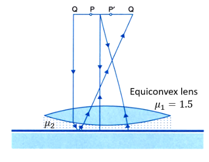
Ans: An equiconvex lens is in touch with a liquid layer on a plane mirror top. A small needle placed on the principal axis is moved along the axis until its inverted image will be at the position of the needle.
Convex lens focal length, \[{{f}_{1}}=30\text{ }cm\]
The liquid will behave as a mirror.
Liquid’s focal length \[=\text{ }f{}_{2}\]
System’s focal length, \[f\text{ }=\text{ }45\text{ }cm\]
The equivalent focal length is given as:
$\frac{1}{f}=\frac{1}{{{f}_{1}}}+\frac{1}{{{f}_{2}}}$
$\Rightarrow \frac{1}{{{f}_{2}}}=\frac{1}{f}-\frac{1}{{{f}_{1}}}$
$\Rightarrow \frac{1}{{{f}_{2}}}=\frac{1}{45}-\frac{1}{30}=-\frac{1}{90}$
$\therefore {{f}_{2}}=-90cm$
Let the lens’s refractive index be ${{\mu }_{1}}$ and curvature radius of one surface be \[R.\]
Hence, the curvature radius of the other surface is \[\text{ }R\].
We use,
$\frac{1}{{{f}_{1}}}=\left( {{\mu }_{1}}-1 \right)\left[ \frac{1}{R}-\frac{1}{-R} \right]$
$\Rightarrow \frac{1}{30}=\left( 1.5-1 \right)\left[ \frac{2}{R} \right]$
$\therefore R=30cm$
Let ${{\mu }_{2}}$ be the liquid’s refractive index.
Liquid’s curvature radius on the side of the plane mirror $=\infty $.
Curvature radius of the liquid on the side of the lens, \[R=-\text{ }30\text{ }cm\].
We use,
$\frac{1}{{{f}_{2}}}=\left( {{\mu }_{2}}-1 \right)\left[ \frac{1}{R}-\frac{1}{\infty } \right]$
$\Rightarrow \frac{-1}{90}=\left( {{\mu }_{2}}-1 \right)\left[ \frac{1}{-30}-0 \right]$
$\Rightarrow \left( {{\mu }_{2}}-1 \right)=\frac{1}{3}$
$\Rightarrow {{\mu }_{2}}=1.33$
Clearly, the liquid’s refractive index is \[1.33.\]
Key Points at a Glance
1. Straight-line Nature of Light:
In optics, light is conceptualized as a straight-line ray.
Every object is associated with an image in this optical model.
2. Reflection Phenomenon:
Reflection is the process of altering the course of light without changing the medium.
Upon striking a surface, light reflects back into the same medium from which it originated.
3. Reflection Laws:
Two fundamental laws govern reflection.
The angle of incidence (I) equals the angle of reflection (r).
At the point of incidence, the incident ray, reflected ray, and the normal to the reflecting surface lie in the same plane.
4. Spherical Mirrors:
Reflecting surfaces of spherical mirrors are enclosed within hollow spheres.
These mirrors come in two types: concave and convex.
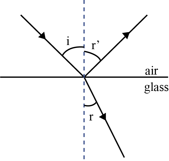
Ray Optics and Optical Instruments Chapter Summary - Class 12 NCERT Solutions
Reflection is governed by the equation ∠i = ∠r′ and refraction by the Snell’s law, $\frac{\sin i}{\sin r}=\mu $ , where the incident ray, reflected ray, refracted ray and normal lie in the same plane, ⎧ is the refractive index of glass medium.
The critical angle of incidence C for a ray incident from a denser to rarer medium, is that angle for which the angle of refraction is 90°. For i > C, total internal reflection occurs.
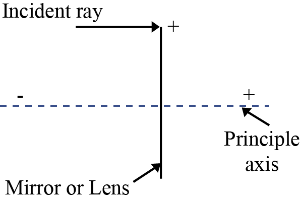
Cartesian Sign Convention: Distance measured in the same direction as the incident light are positive; those measured in the opposite direction are negative. All distances are measured from the pole/optical centre of the mirror/lens on the principal axis. The heights measured upwards above x-axis and normal to the principal axis of the mirror/lens are taken as positive. The heights measured downwards are taken as negative.
Mirror Equation:
$\frac{1}{v}+\frac{1}{u} = \frac{1}{f}$
where u and v are object and image distances, respectively, and f is the focal length of the mirror. f is (approximately) half the radius of curvature R. f is negative for a concave mirror; f is positive for a convex mirror.
For a prism of the angle A, of refractive index $\mu_2$ placed in a medium of refractive index $\mu_1$,
$\mu_{21}=\frac{\mu_2}{\mu_1}=\frac{\sin \left [ \frac{(A + \delta_m)}{2} \right ]}{sin\left (\frac{A}{2} \right )}$
Where $\delta_m$ is the angle of minimum deviation.

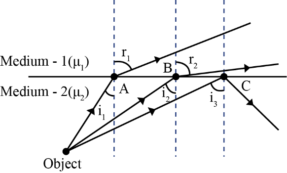
For refraction through a spherical interface (from medium 1 to 2 of refractive index
$\mu _{1}$ and $\mu _{2}$ , respectively
$\frac{\mu_2}{v}-\frac{\mu_1}{u}=\frac{\mu_2 - \mu_1}{R}$
Thin lens formula
$\frac{1}{v}-\frac{1}{u}=\frac{1}{f}$
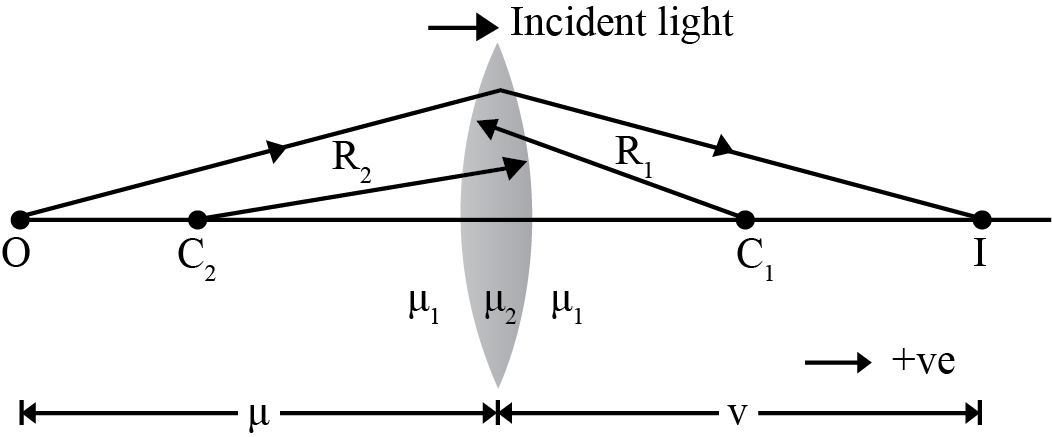
Lens maker’s formula
$\frac{1}{f}=\frac{\mu_2 - \mu_1}{\mu_1}\left ( \frac{1}{R_1}-\frac{1}{R_2} \right )$
Where, f is positive for a converging lens; f is negative for a diverging lens.
The power of a lens $P=\frac{1}{f}$.
The SI unit for power of a lens is dioptre (D)
1 D = 1 m–1 .
If several thin lenses of focal length f1 , f2 , f3 ,.. are in contact, the effective focal length of their combination, is given by $\frac{1}{f}=\frac{1}{f_1}+\frac{1}{f_2}+\frac{1}{f_3}+...$
The total power of a combination of several lenses is
P = P1 + P2 + P3 + …
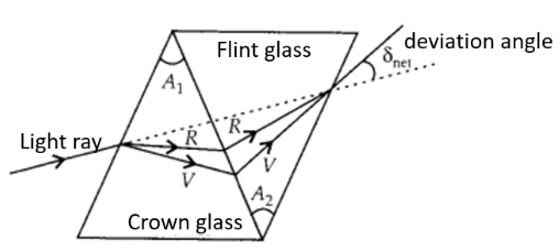
Dispersion is the splitting of light into its constituent colour.
Magnifying power m of a simple microscope is given by $m=1+\frac{D}{f}$, where D = 25 cm is the least distance of distinct vision and f is the focal length of the convex lens.
If the image is at infinity, $m=\frac{D}{f}$.

For a compound microscope, the magnifying power is given by $m=m_e\times m_0$, where $m_e = 1+\frac{D}{f_e}$, is the magnification due to the eyepiece and $m_0$ is the magnification produced by the objective. Approximately,
$m=\frac{L}{f_0}=\frac{D}{f_e}$
Where fo and fe are the focal lengths of the objective and eyepiece, respectively, and L is the distance between their focal points.
Magnifying power m of a telescope is the ratio of the angle ® subtended at the eye by the image to the angle 〈 subtended at the eye by the object.
$m=\frac{\beta}{\alpha}=\frac{f_0}{f_e}$
Where fo and fe are the focal lengths of the objective and eyepiece, respectively.
Overview of Deleted Syllabus for CBSE Class 12 Physics Ray Optics and Optical Instruments
Conclusion
NCERT Class 11 Physics Chapter 2 Exercise Solutions on Ray Optics and Optical Instruments provided by Vedantu provides a thorough understanding of how light behaves and interacts with different media. The chapter covers fundamental principles and their applications, equipping students with the knowledge to understand and work with various optical instruments. This chapter introduces the fundamental concepts of ray optics, focusing on the behaviour of light as it travels through different media and interfaces. These concepts are essential for mastering the topic and are often tested in exams. From previous year's question papers, typically around 3–4 questions are asked from this chapter.
Other Study Material for CBSE Class 12 Physics Chapter 9
Chapter-Specific NCERT Solutions for Class 12 Physics
Given below are the chapter-wise NCERT Solutions for Class 12 Physics. Go through these chapter-wise solutions to be thoroughly familiar with the concepts.
Related Links for NCERT Class 12 Physics in Hindi
Discover relevant links for NCERT Class 12 Physics in Hindi, offering comprehensive study materials, solutions, and resources to enhance understanding and aid in exam preparation.
Chapter-Specific NCERT Solutions for Class 12 Physics
Given below are the chapter-wise NCERT Solutions for Class 12 Physics. Go through these chapter-wise solutions to be thoroughly familiar with the concepts.

FAQs on NCERT Solutions For Class 12 Physics Chapter 9 Ray Optics And Optical Instruments - 2025-26
1. What are NCERT Solutions for Class 12 Physics Chapter 9 Ray Optics and Optical Instruments as per the CBSE 2025–26 syllabus?
NCERT Solutions for Class 12 Physics Chapter 9 provide step-by-step answers and detailed explanations for every question and numerical in Ray Optics and Optical Instruments, strictly following the CBSE 2025–26 syllabus. These solutions help students master core concepts such as reflection, refraction, mirror and lens formulas, optical instruments, and total internal reflection, ensuring conceptual clarity and exam readiness.
2. How is the mirror formula used to solve image formation questions in Class 12 Physics?
The mirror formula is: 1/v + 1/u = 1/f, where u is object distance, v is image distance, and f is focal length. Assign appropriate signs based on the CBSE Cartesian convention, substitute known values, and solve for the unknown parameter (image position, focal length, or object distance) to accurately analyze image formation by spherical mirrors.
3. What is the significance of sign conventions in solving ray optics numericals at the Class 12 level?
Applying the Cartesian sign convention is essential in mirror and lens formulas for Class 12. All measurements are made from the pole (mirrors) or optical centre (lenses): distances measured in the direction of incident light are positive, while those opposite are negative. Consistently using correct signs helps avoid calculation errors in multi-step numericals and ensures correct interpretation of image nature and position.
4. Which topics from Ray Optics and Optical Instruments are most frequently asked in CBSE board exams?
- Derivation and application of mirror and lens formulas
- Total internal reflection and its uses (e.g., optical fibres)
- Numericals on optical instruments (compound microscope, telescope)
- Ray diagrams for concave/convex lens and mirror image formation
- Sign convention applications in numericals
5. How do you determine the magnifying power of a compound microscope?
The magnifying power (m) is the product of the magnification due to the objective (m₀) and eyepiece (mₑ):
m = m₀ × mₑ, where
m₀ = v₀/|u₀| (objective), mₑ = 1 + D/fₑ (D = least distance of distinct vision, usually 25 cm; fₑ = focal length of eyepiece). Insert given values to calculate total magnifying power as per CBSE problem instructions.
6. What steps should be followed to solve lens combination problems in NCERT Solutions for Ray Optics?
- Identify the type and focal lengths (f₁, f₂, …) of the lenses involved
- If lenses are in contact, use: 1/f = 1/f₁ + 1/f₂ + ...
- Apply sign conventions correctly (converging lens: +ve f; diverging: –ve f)
- Use the lens or mirror formula as required
- Assign correct refractive indices if the surrounding medium isn't air
- Calculate effective focal length, position of image, or magnification as needed
7. Why does total internal reflection occur, and how is it used in optical instruments?
Total internal reflection (TIR) occurs when light passes from a denser medium to a rarer one at an angle greater than the critical angle, causing all light to reflect back internally. TIR is exploited in optical instruments such as fibre optics for lossless signal transmission and in certain prism-based devices to enhance image brightness and clarity by preventing loss of light.
8. What are common misconceptions students have when applying the lens maker’s formula?
- Applying wrong signs to radii of curvature (remember: R₁ is positive if centre of curvature is to the right, negative if to the left; opposite for R₂)
- Ignoring the refractive indices of lens and surrounding medium
- Using the formula for thick lenses (it is valid only for thin lenses as per NCERT guidelines)
- Not checking the formula’s assumptions (e.g., paraxial rays, homogeneous medium)
9. How can you distinguish between real and virtual images in Ray Optics problems?
Real images are formed by actual convergence of rays (can be projected on a screen); for mirrors, this typically gives negative v values, and for lenses, positive v values on the opposite side. Virtual images are formed by apparent divergence, cannot be caught on a screen, and have positive v for mirrors and negative v for lenses. Following sign convention and physical reasoning from NCERT Solutions helps determine image type.
10. What changes in standard Ray Optics equations if the medium around a lens or mirror is not air?
If the lens or mirror is surrounded by a medium with refractive index ≠ 1 (not air), the formulas adjust by replacing the refractive index of air with that of the surrounding. For example, the lens maker’s formula modifies to account for the ratio of the indices: f = (μ₂/μ₁ – 1) ... . This affects both focal length calculation and the nature of image formation, as explained in advanced NCERT problems.
11. What key differences exist between ray optics and wave optics as explained in Class 12 NCERT Solutions?
Ray optics treats light as straight lines (rays), focusing on geometric image formation using laws like reflection and refraction. Wave optics considers light as a wave, explaining phenomena such as interference, diffraction, and polarization. NCERT Solutions distinguish their applications: ray optics is used for image location and instrument design, while wave optics explains patterns and color effects not predicted by rays.
12. How is the power of a lens defined and used in Class 12 Physics problems?
The power (P) of a lens is defined as P = 1/f (with f in metres), measured in dioptres (D). Convex (converging) lenses have positive power; concave (diverging) lenses have negative power. In NCERT and board questions, total power of lenses in contact is found by adding individual powers: P = P₁ + P₂ + ...
13. Why is understanding the human eye important in Ray Optics for CBSE Class 12?
The human eye is a natural optical instrument illustrating principles of image formation with lenses. Board questions may require calculation or explanation of vision correction (e.g., myopia, hypermetropia) using ray optics concepts and formulas, as modelled in NCERT Solutions, making it directly relevant for both conceptual understanding and application.
14. How should you approach conceptual 'what if' questions in NCERT Solutions for Ray Optics and Optical Instruments?
- State physical assumptions (medium, refractive index, thin lens, paraxial rays)
- Use a ray diagram to visualize the scenario
- Apply correct lens/mirror equations and sign conventions
- Explain the physics behind the calculation, not just the math
15. In what situations might the ray approximation used in Ray Optics break down?
- When object or aperture size is comparable to the wavelength of light (diffraction/wave optics phenomena)
- When rays pass close to the lens/mirror edge (causing significant spherical aberration)
- At very high precision or non-visible wavelengths