


Step-by-Step Guide to Series Combination of Resistances for Exam Success
A metre bridge is a device which works on the Wheatstone bridge idea. It is generally used to find the unknown resistance of a conductor. This device consists of a wire of one metre, which is why it is known as a “metre bridge”. The wire used to make the metre bridge is either nichrome, manganin or constantan. It is referred to as a slide wire bridge. This device is designed from a Wheatstone bridge.
In this article, we will have a deep insight into the metre bridge formula and procedure to perform an experiment to verify the law of combination (series) of resistances using it.
Table of Contents:
Aim
Apparatus Required
Theory
Procedure
Observations
Result
Precautions
Lab Manual Questions
Viva Questions
Practical Based Questions
Aim
Metre Bridge Formula - To verify the laws of combination (series) of resistances using a metre bridge.
Apparatus Required
Resistance box
Leclanche cell and jockey
Metre Bridge
Galvanometer and a key
Sandpaper and connecting wires
Two resistance wires or two resistance coils
A set square
Theory
A metre bridge is based on the principle of Wheatstone bridge. The general arrangement of the Wheatstone bridge is shown in the figure below. It consists of four arms, DA, AB, BC and CD consisting of known and fixed resistances R1 and R3 and variable resistance R2 and unknown resistance Rx. The sensitive galvanometer is connected across terminals D and B. The battery is connected across other two terminals, A and C.

Wheatstone Bridge
Wheatstone bridge is also used to measure capacitance and impedance and is based on the principle of null deflection. That means no current will flow through the middle arm of the circuit when the ratio of resistances in the two arms is equal. No current will flow through the galvanometer in the balanced condition. This situation arises when we get R1/R2 = R3/Rx, which is the balanced condition of the Wheatstone bridge. So, in this way, the unknown resistance Rx can be determined in terms of other known resistances of the Wheatstone bridge.
A metre bridge consists of one metre-long constantan wire of uniform cross-sectional area mounted on a wooden board with a scale.
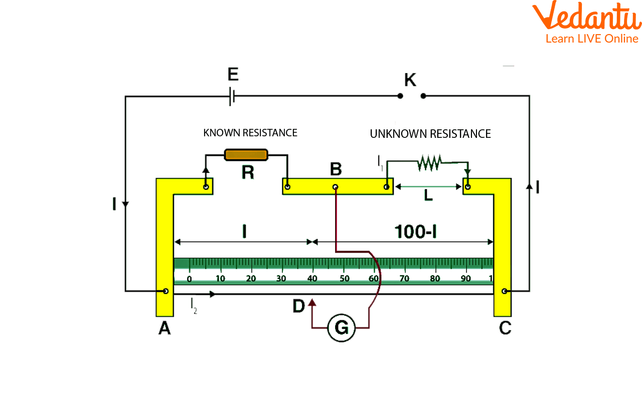
Circuit Diagram Of Metre Bridge
Two ends of the wire are attached to terminals A and C which is shown here in the above circuit diagram. In the metre bridge, thick metal strips bent at right angles are used to provide two gaps to connect resistors. The terminal B which is between the gaps is used to connect the galvanometer and we should connect the other end of the galvanometer to a Jockey J.
Series Combination of Resistances:
We know that, when two resistors and are connected in series, the resistance of their combination is given by,
The resistance of an unknown resistance wire or a coil is expressed by, (from the above figure)
Where, is the resistance from the resistance box in the left gap and is the length of the metre bridge wire from zero ends up to the balance point.
Procedure
First of all, we need to mark the two resistance coils as and .
Now, connect the wire in the right gap between C and B, whose resistance is to be determined, and we should connect the resistance box in the left gap between A and B as shown in the circuit diagram of the metre bridge. The arrangement of the other apparatus should be as shown in the circuit diagram of the metre bridge.
Carefully tighten all the plugs in the resistance box by pressing and rotating each plug to ensure that all the plugs make good electrical connections. Then, using sandpaper, clean the ends of connecting wires before making the connections.
After that, we need to remove some plugs from the resistance box and plug the key K.
Now, slide the jockey gently along the wire from left to right till the galvanometer gives zero deflection. The deflections in the galvanometer should be in opposite directions and if it is in one direction, then we can say that the circuit connections are not correct.
Let D be the null point where the jockey is touching the wire and the movement of the jockey should be gentle from left to the right of the galvanometer and obtain a null point D on the metre bridge wire by sliding it gently between the ends A and C.
Note the value of resistance and lengths AD and DC and calculate the experimental value of the equivalent series resistance.
Repeat this experiment for two more values of resistance and obtain the mean value of unknown resistance.
Repeat the above steps by connecting and then by connecting resistances and in series in the right gap between C and B and record the observations as given in the table below.
Observations
Resistance Coil | S.I. | Resistance From The Resistance Box | Length AD =
| Length DC = | Resistance (ohm) | Mean Resistance (ohm) |
only | 1. | = ___ | ||||
2. | ||||||
3. | ||||||
only | 1. | = ___ | ||||
2. | ||||||
3. | ||||||
and in series | 1. | = ___ | ||||
2. | ||||||
3. |
The theoretically expected value of the series combination resistances is
Here, we can obtain and from colour code on carbon resistors or are the given values in case of resistances made of wires of materials like nichrome, constantan etc.
Result
We can conclude from the experiment that within limits of experimental error, theoretical and experimental values of are the same. Hence, we can say that we have verified a series combination of resistances using the metre bridge. So, the law of resistance in series is verified.
Precautions
All the connections and plugs should be neat, clean and tight.
The jockey should be moved gently over the metre bridge wire.
Plug keys of the resistance box should be tight by rotating it in a clockwise direction, and null points should be in the central region of the wire.
Lab Manual Questions
1. Why should the jockey not be pressed too hard on the wire when sliding over it?
Ans: It alters the area of the cross-section of the wire, which in turn changes the resistance per unit length of the wire. So, we should not rub the jockey on the metre bridge’s wire.
2. From which metal metre bridge’s wire is formed?
Ans: Nichrome, constantan and manganin are generally used to form metre bridge’s wire because they have very low temperature coefficient.
3. What is a galvanometer?
Ans: A galvanometer is an accurate and sensitive instrument which is used to measure and detect electric current.
4. When is Wheatstone Bridge said to be balanced?
Ans: The Wheatstone bridge is said to be balanced when no current flows through the galvanometer.
Viva Questions
1. What is Metre Bridge?
Ans: Metre bridge is an instrument through which we can find the resistance of any given wire. It is a modified form of Wheatstone’s network.
2. On which principle does the metre bridge work?
Ans: Metre bridge works on the Wheatstone’s bridge principle.
3. What is the need of a combination of resistances?
Ans: The need of combination of resistances is to get the desired range of required resistance for the electrical circuit.
4. Which quantity remains the same in a series combination of resistors?
Ans: Current (I) remains the same in a series combination of resistors.
5. Why do we use a galvanometer in this experiment?
Ans: To find a balanced point or zero deflection point, we use the galvanometer in this experiment.
6. Which is the latest version of the metre bridge?
Ans: Carey Foster Bridge is the latest version of the metre bridge.
7. What type of galvanometer is generally used in a laboratory?
Ans: Pivoted Coil Weston type galvanometer is generally used in a laboratory.
8. What is resistance?
Ans: It is a property of a conductor by virtue of which it resists the flow of current through it. Its SI unit is ohm.
9. What happens to the equivalent resistance when we connect three resistances in series combination?
Ans: The equivalent resistance increases when we connect three resistances in series combination.
10. Why do we use copper blades in the metre bridge?
Ans: We use copper blades in the metre bridge because the resistance of copper is negligible.
Practical Based Questions
Where can we obtain the balance point in the metre bridge?
At right end of the wire
At any point of the wire
At left end of the wire
At the mid point of the wire
Ans: Option D - At the mid point of the wire
_____ is independent of the radius of the wire.
The balance point of the metre bridge
The unbalanced point of the metre bridge
Fuse of the metre bridge
None of the above
Ans: Option A - The balance point of the metre bridge
_____ value of resistance can be found using the metre bridge.
Moderate
High
Low
All of the above
Ans: Option A - Moderate
Which instrument can be used to measure resistance?
Voltmeter
Voltameter
Ammeter
Ohmmeter
Ans: Option D - Ohmmeter
The symbol for voltage is?
W
VO
V
Amp
Ans: Option C - V
What happens if we connect two or more resistances in series combination?
The voltage through each resistance would be same
The current through each resistance would be same
Option A and B
None of the above
Ans: Option B - The current through each resistance would be same
Which of the following statements are correct?
The metre bridge is based on the principle of Wheatstone bridge
The metre bridge is used to find unknown resistance and it is also called a slide wire bridge
Option A and B
None of the above
Ans: Option C - Option A and B
When two resistances are connected in the series combination, then the effective resistance _____.
Increases
Decreases
Becomes half
Does not change
Ans: Option A - Increases
We should connect an ammeter in _____ across the cell.
Series
Triangular
Either series or triangular
Parallel
Ans: Option A - Series
What do we measure using a Wheatstone Bridge?
Radius of the bridge wire
Voltage
Power
Resistance
Ans: Option D - Resistance
Conclusion
From the above experiment, we can conclude that the difference of theoretical and experimental value in series combination is very small. So, the law of series combination of resistances is verified.
FAQs on Understand Series Resistance Using the Metre Bridge: Class 12 Physics 2026-27
1. What is the principle behind using a metre bridge to verify the law of combination (series) of resistances in Class 12 board exams?
The metre bridge operates on the Wheatstone bridge principle, where it is used to determine unknown resistances by achieving a balanced condition (no current through the galvanometer) and applying the relation R1/R2 = R3/Rx, essential for verifying the series combination of resistances as per CBSE syllabus.
2. Describe the stepwise experimental procedure for verifying the law of combination (series) of resistances using a metre bridge, important for board marks.
The procedure includes:
- Arranging apparatus with resistance coils r1 and r2 in series in the right gap
- Connecting a resistance box in the left gap
- Tightening all connections and cleaning wire ends for accuracy
- Sliding the jockey to find the null point on the wire
- Measuring lengths for balanced condition and calculating unknown resistance
- Repeating for different resistance values to obtain the mean
3. Why are alloys like manganin or constantan preferred over copper for the wire in a metre bridge, as per board conceptual questions?
Alloys such as manganin and constantan are used because they have a low temperature coefficient of resistance and maintain a uniform resistance per unit length. Copper is not preferred due to its high temperature coefficient, which can introduce errors and affect measurement reliability in high-precision experiments.
4. State the formula for calculating equivalent resistance when two resistors are connected in series and explain its importance in board answers.
The equivalent resistance Rs of two resistors in series is given by Rs = r1 + r2. This formula is fundamental for solving circuit problems and verifying experimental results in Class 12 Physics board exams.
5. What precautions must be taken while performing the metre bridge experiment to ensure accurate results as expected in high-mark board questions?
Important precautions include:
- Ensuring all connections are tight and clean
- Not pressing the jockey too hard on the wire
- Cleaning and tightening the resistance box plugs
- Moving the jockey gently to avoid damaging the wire
- Placing the null point near the middle of the wire for best sensitivity
6. How do you identify and minimize end error in a metre bridge, as asked in board HOTS questions?
An end error occurs if the meter scale zero does not align with the starting point of the wire or due to stray resistances. To minimize end error, start measurements carefully from the exact end and ensure the apparatus is free from extraneous connections or resistances.
7. During the experiment, if the galvanometer shows deflection only in one direction, what does it indicate and how should you troubleshoot this scenario in the exam?
If the galvanometer deflects only in one direction, it indicates incorrect circuit connections or an unbalanced bridge. Recheck the wiring, clean connection points, and ensure resistors and galvanometer leads are placed as per the standard circuit diagram for series combination of resistors.
8. Explain why the current remains the same through each resistor when they are connected in series, which is often tested in board reasoning questions.
In a series circuit, current flows through a single path, so every resistor receives the same current. This property simplifies calculations and is crucial for predicting circuit behavior in board examination problems.
9. What would happen to the equivalent resistance if you keep adding more resistors in series, and why is this effect significant in practical circuits?
Adding more resistors in series increases the total or equivalent resistance. This is because total resistance is the sum of all individual resistances (Rs = r1 + r2 + r3 + ...). Higher resistance restricts current flow, which is important when circuit design requires limited current for safety or function.
10. What are common sources of error in the series combination metre bridge experiment, and how can students address these in board exam answers?
Common errors include:
- End errors due to misaligned scale and wire
- Poor connection or loose plugs
- Non-uniform wire cross-section
- External magnetic fields affecting the galvanometer
11. Why is achieving the null deflection in the galvanometer important during the experiment for verifying the law of series combination?
Null deflection indicates that the ratio of resistances in the circuit arms satisfies the Wheatstone bridge’s balanced condition, making the calculation of unknown resistance accurate. This ensures the experimental verification matches theoretical expectations, as required in CBSE practical and theory exams.
12. How do you calculate the resistance of an unknown wire using a metre bridge, as per exam-oriented practical questions?
Measure the length ‘l’ from one end of the metre bridge to the null point. Use the formula r = [(100 – l)/l] × R, where R is the known resistance in the other arm. This allows precise determination of the unknown resistance for board questions.
13. What conceptual misunderstanding about resistances in series could lead to mistakes in board answers?
A common error is thinking that voltage is the same across all series resistors, which is incorrect. Current is the same in series, but voltage divides proportionally to resistance. Understanding this difference prevents calculation mistakes in exam responses.
14. In what ways does the series combination of resistances experiment using a metre bridge benefit real-world electrical circuit applications?
This experiment helps students understand how to combine resistors practically to obtain desired resistance values in circuits, which is necessary for protecting devices, controlling current, and power distribution in household and industrial applications, connecting board theory to applied physics.