


Class 7 Maths (Ganita Prakash II) Chapter 6 Constructions and Tilings Solutions
Figure It Out
1. When constructing the perpendicular bisector, is it necessary to have the same radius for the arcs above and below XY? Explore this through construction, and then justify your answer.
[Hint 1: Any point that is of the same distance from X and Y lies on the perpendicular bisector.
Hint 2: We can draw the whole line if any two of its points are known.]
Solution
Draw a line segment XY.
Choose two radii, k and k′, each slightly greater than half the length of XY.
With X and Y as centres, draw arcs of radius k below XY.
Using the same centres, X and Y, draw arcs of radius k′ below XY.
Let the arcs above XY intersect at A and the arcs below XY intersect at B.
Join A and B, and mark the point where AB intersects XY as O.
Join AX, AY, BX and BY.
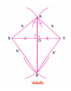
∆ABX and ∆ABY are congruent because AX = AY = k, BX = BY = k′, and AB is common.
∴ ∠XAO = ∠YAO
∆AOX and ∆AOY are congruent because AX = AY = k, ∠XAO = ∠YAO, and OA is common.
∴ OX = OY and ∠AOX = ∠AOY
Also, ∠AOX + ∠AOY = 180°
∴ 2∠AOX = 180° or ∠AOX = 90°
∴ OX = OY and ∠AOX = ∠AOY = 90°.
∴ AB is the perpendicular bisector of the line XY.
Here, A and B are points that are equidistant from X and Y.
Thus, any point that is equidistant from X and Y lies on the perpendicular bisector.
2. Is it necessary to construct the pairs of arcs above and below XY? Instead, can we construct both pairs of arcs on the same side of XY? Explore this through construction, and then justify your answer.
Solution
Draw a line segment XY.
Choose distances k and k′ that are slightly greater than half the length of XY.
With X and Y as centres, draw arcs of radius k above XY.
With A and Y as centres, draw arcs of radius k′ above XY.
Let the arcs intersect at points A and B.
Join A and B, and extend this line to intersect XY at O.
Join AX, AY, BX and BY.
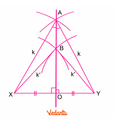
∆ABX and ∆ABY are congruent because AX = AY = k, BX = BY = k′, and AB is common.
∴ ∠XAO = ∠YAO
∆AOX and ∆AOY are congruent because AX = AY = k, ∠XAO = ∠YAO, and OA is common.
∴ OX = OY and ∠AOX = ∠AOY
Also, ∠AOX + ∠AOY = 180°
∴ 2∠AOX = 180° or ∠AOX = 90°
∴ OX = OY and ∠AOX = ∠AOY = 90°
∴ AB is the perpendicular bisector of the line XY.
Here, both pairs of arcs are constructed on the same side of XY.
∴ It is not necessary to construct the pairs of arcs above and below XY.
3. While constructing one pair of intersecting arcs, is it necessary that we use the same radii for both of them? Explore this through construction, and then justify your answer.
Solution
Draw a line segment XY.
With centres at X and Y, draw arcs of unequal radii, say k and k’.
Let the arcs intersect at the point A.
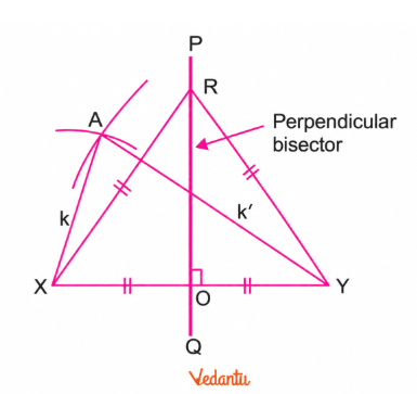
Let PQ be the perpendicular bisector of XY.
Let R be any point on PQ.
Join RX and RY.
∆ROX and ∆ROY are congruent, because OX = OY, ∠ROX = ∠ROY, and OR is common.
∴ RX = RY
∴ For any point R on the perpendicular bisector, we have RX = RY.
∴ Every point on the perpendicular bisector is equidistant from X and Y.
Since AX ≠ AY, the point A is not on the perpendicular bisector.
Thus, to construct a perpendicular bisector, we must use the same radius for both arcs of a pair of arcs.
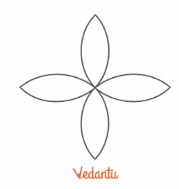
4. Recreate this design using only a ruler and compass-
Solution:
Let ABCD be a square. Draw the perpendicular bisectors of sides AB and BC, as shown in the figure.
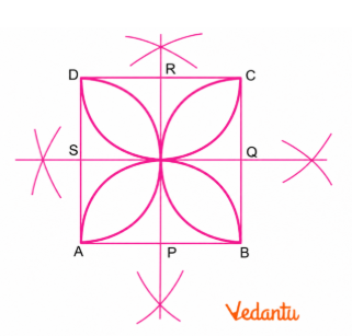
Let the perpendicular bisectors intersect the square at the points P, Q, R, and S.
With centres at P, Q, R, and S, draw semicircles in the square with radius equal to AP.
Colour the boundary of the design using a coloured pencil.
This will make the design stand out from the supporting lines and curve.
Figure It Out
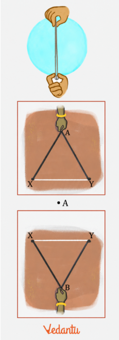
1. Justify why AB in Fig. 6.4 is the perpendicular bisector
Solution
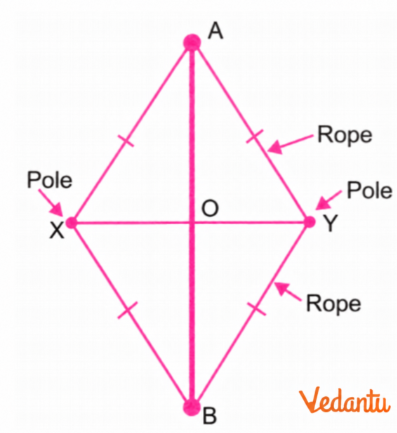
In the above figure, XAY and XBY are two positions of the rope.
Points A and B are at the midpoint of the rope.
∴ We have AX = AY = BX = BY.
∆AXB and ∆AYB are congruent, because AX = AY, BX = BY, and AB is common.
∴ ∠XAO = ∠YAO
∆AXO and ∆AYO are congruent, because AX = AY, ∠XAO = ∠YAO, and AO is common.
∴ OX = OY and ∠XOA = ∠YOA.
Also, ∠XOA + ∠YOA = 180°
∴ 2∠XOA = 180° or ∠XOA = 90°
∴ OX = OY and ∠XOA = ∠YOA = 90°
∴ By definition, AB is the perpendicular bisector of the line XY.
2. Can you think of different methods to construct a 90° angle at a given point on a line using a rope?
Solution
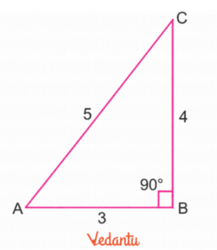
In this construction, we shall use the 3-4-5 principle that if the sides of a triangle are in the ratio 3 : 4 : 5, then the angle opposite to the longest side is 90°.
In the figure, the sides AB, BC, and CA are in the ratio 3 : 4 : 5 and the angle B, opposite to the longest side AC, is equal to 90°.
Construction:
Draw a line XY and take any point A on it.
We shall construct a 90° angle at point A, using a rope.
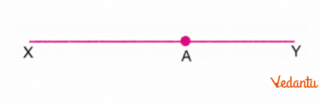
Fix a small pole at point A.
Take a rope and mark it at 0 units, 3 units, 8 units, and 12 units.
Attach the 0 unit mark and 12 unit mark of the rope at A.
Attach the 3-unit mark at point B on the line XY, with the help of a pole at B.
Now hold the 8-unit point of the rope and extend it away from XY so that both sides of this point are tight.
Place a pole at this point and call this point C, as shown in the figure.
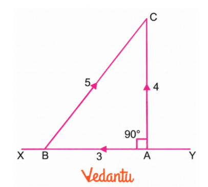
In the ∆ABC, the sides are 3 units, 4 units, and 5 units.
The angle opposite to the longest side is ∠A.
∴ By the 3-4-5 principle, ∠A is equal to 90°.
∴ The line AC is perpendicular to the line XY at the given point A.
Figure It Out
1. Construct at least 4 different angles. Draw their bisectors.
Solution
We draw 4 different angles, ∠ABC, ∠DEF, ∠GHI, and ∠JKL, as shown below:
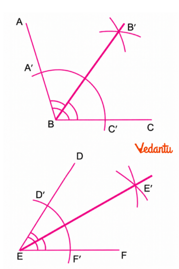
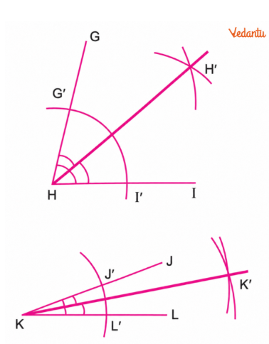
We shall draw the bisectors of the above angles.
With centres at B, E, H, and K, draw arcs intersecting the arms of the angles.
With centres at A’, C’, D’, F’, G’, I’, J’, and L’, draw arcs of the same radius so that the arcs intersect at points B’, E’, H’, and K’.
Join BB’, EE’, HH’, and KK’.
In the above figure:
BB’ is the bisector of ∠ABC
EE’ is the bisector of ∠DEF
HH’ is the bisector of ∠GHI
KK’ is the bisector of ∠JKL
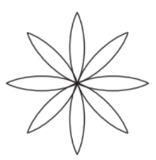
2. Construct the 8-petalled figure shown in Fig. 6.5.
Solution
Draw a line AB.
With centres at A and B, draw arcs of equal radius above and below the line AB.
Let the arcs intersect at the points C and D.
Join C and D.
Let AB and CD intersect at O.
Draw the bisectors of ∠BOC, ∠COA, ∠AOD, and ∠DOB as shown in the figure.
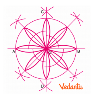
Draw a circle with centre at O and radius equal to the length of a petal in the given figure.
Draw dots at the points of intersection of the circle with the lines.
Using the dots and the centre of the circle, draw the petals as shown in the given figure.
In the next step, we erase the extra lines and arcs.
The above figure looks as given below:
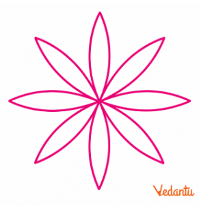
This is the required 8-petalled figure.
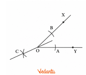
3. In the process of angle bisection, if arcs of equal radius are drawn on the other side, as shown in the figure, will the line OC still be an angle bisector? Explore this through construction, and then justify your answer.
Solution
Let ∠XOY be any angle. With centre at O, draw an arc intersecting the lines OX and OY at A and B respectively.
With centres at A and B, draw arcs of the same radius so that the arcs intersect at a point, say C.
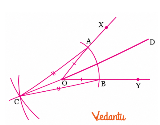
Join AC, BC, and OC. Extend CO to CD.
We have OA = OB and AC = BC.
In ∆OAC and ∆OBC, we have OA = OB, AC = BC, and OC is common.
∴ ∆OAC ≅ ∆OBC (Using SSS rule)
∴ ∠AOC = ∠BOC
∴ 180° – ∠AOC = 180° – ∠BOC
∴ ∠AOD = ∠BOD
∴ Line OD is the bisector of the angle ∠XOY.
∴ Line OC is the bisector of the angle ∠XOY.
4. What are the other angles that can be constructed using angle bisection? Can you construct a 65.5° angle?
Solution
Using the angle bisector method, we can divide a given angle into two equal parts.
Using a ruler and compass, we can construct a 90° angle on a line.
90° ÷ 2 = 45°
45° ÷ 2 = 22.5°
Therefore, using angle bisection, we can construct angles of 45° and 22.5°.
Also,
90° + 45° = 135°
90° + 22.5° = 112.5°
45° + 22.5° = 67.5°
Hence, we can also construct angles of 135°, 112.5°, and 67.5°.
However, a 65.5° angle cannot be constructed using this angle-bisection method.
5. Come up with a method to construct the angle bisector using a rope.
Solution
Let ∠XOY be the given angle.
Fix a small pole at point O.
Take a rope and make a loop at one end.
Mark a point at a fixed distance on the rope.
Fix the loop of the rope to the pole at O and rotate the rope from OX to OY.
Mark points A and B on the two arms of the angle using the fixed distance marked on the rope.
Fix small poles at A and B.
Take another piece of rope and make loops at both ends.
Fix these loops to the poles at A and B.
Find the midpoint of this rope and mark it.
Pull both ends of the rope tight and mark the midpoint as M.
Join AM, BM, and OM.
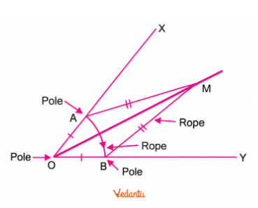
Here,
OA = OB
and
AM = BM
In ∆OAM and ∆OBM,
OA = OB
AM = BM
OM is common.
Therefore,
∆OAM = ∆OBM, by the SSS congruence rule.
Hence,
∠AOM = ∠BOM
Therefore,
∠XOM = ∠YOM
Thus, OM is the angle bisector of ∠XOY.
6. Construct the following figure:
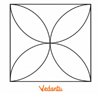
How do we construct the petals so that they are of the maximum possible size within a given square?
Solution
Draw a straight line and mark points A and B on it.
Taking A and B as centres, draw semicircles intersecting the line at C, D, E, and F.
With C and D as centres, draw arcs of equal radius meeting at G.
With E and F as centres, draw arcs of equal radius meeting at H.
Join AG and BH.
Mark points I and J on AG and BH respectively so that AI = BJ = AB.
Join I and J.
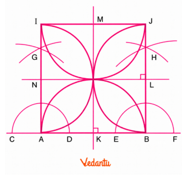
ABJI is a square.
Using a ruler and compass, construct the perpendicular bisectors of sides AB and BJ.
With K, L, M, and N as centres, draw semicircles inside the square with radius equal to AK.
Erase the unnecessary construction lines and arcs.
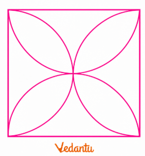
The required figure with four petals is obtained.
The four semicircles are drawn using the maximum possible radius inside the square. Therefore, the petals are of the maximum possible size.
Figure It Out
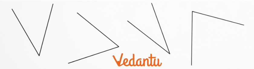
1. Construct at least 4 different angles in different orientations without taking any measurements. Make a copy of all these angles.
Solution
The following are four different angles drawn in different orientations.
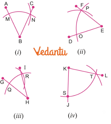
We can copy each of these angles using a ruler and compass.
Angle (i):
Draw a line A’B’ in the direction of AB.
With B and B’ as centres, draw arcs of equal radius.
Let the arc at B intersect AB and BC at M and N respectively.
Let the corresponding arc at B’ intersect A’B’ at M’.
Measure MN using a compass.
Transfer this distance from M’ on the new arc to locate N’.
M’N’ = MN
Join B’ and N’.
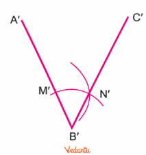
∠A’B’C’ is the required copied angle.
Angle (ii):
Draw a line D’E’ in the direction of DE.
With E and E’ as centres, draw arcs of equal radius.
Let the arc at E intersect the two arms of the angle at O and P.
Let the corresponding arc at E’ intersect D’E’ at O’.
Measure OP using a compass.
Transfer this distance from O’ on the new arc to locate P’.
O’P’ = OP
Join E’ and P’.
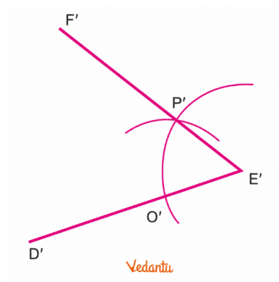
∠D’E’F’ is the required copied angle.
Angle (iii):
Draw a line G’H’ in the direction of GH.
With H and H’ as centres, draw arcs of equal radius.
Let the arc at H intersect GH and HI at Q and R respectively.
Let the corresponding arc at H’ intersect G’H’ at Q’.
Measure QR using a compass.
Transfer this distance from Q’ on the new arc to locate R’.
Q’R’ = QR
Join H’ and R’.
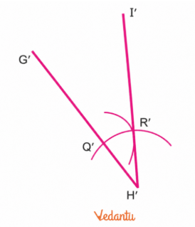
∠G’H’I’ is the required copied angle.
Angle (iv):
Draw a line J’K’ in the direction of JK.
With K and K’ as centres, draw arcs of equal radius.
Let the arc at K intersect JK and KL at S and T respectively.
Let the corresponding arc at K’ intersect J’K’ at S’.
Measure ST using a compass.
Transfer this distance from S’ on the new arc to locate T’.
S’T’ = ST
Join K’ and T’.
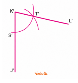
∠J’K’L’ is the required copied angle.
2. Construct the Fig. 6.6.
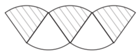
Solution
Let the vertices of the given figure be A, B, C, D, E, F, and G.
Draw A’B’ equal to AB and in the same direction as AB.
With B’ as centre, draw an arc of radius A’B’.
Measure AC using a compass.
Transfer this distance on the arc from A’ to locate C’.
A’C’ = AC
Join B’ and C’. Shade the required sector.
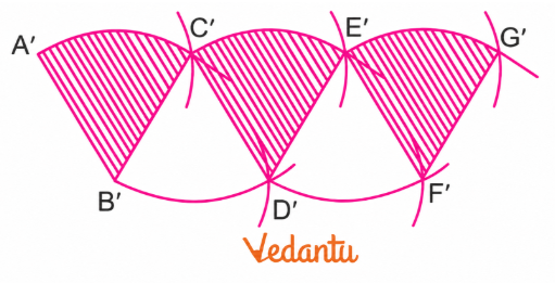
With C’ as centre, draw an arc of radius B’C’.
Measure BD using a compass and transfer this distance from B’ to locate D’.
Join C’ and A’.
With D’ as centre, draw an arc of radius C’D’.
Measure CE using a compass and transfer this distance from C’ to locate E’.
Join D’ and E’. Shade the required sector.
With E’ as centre, draw an arc of radius D’E’.
Measure DF using a compass and transfer this distance from D’ to locate F’.
Join E’ and F’.
With F’ as centre, draw an arc of radius E’F’.
Measure EG using a compass and transfer this distance from E’ to locate G’.
Join F’ and G’. Shade the required sector.
Erase the unnecessary construction arcs.
The required figure is obtained.
Figure It Out
1. Construct 4 pairs of parallel lines in different orientations.
Solution
Let AB be the given line. We first construct another line parallel to AB.
Draw a line CD intersecting AB.
Choose a point P on CD.
Through P, construct a line parallel to AB.
With E and P as centres, draw arcs of equal radius.
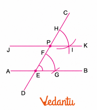
Measure FG using a compass.
Transfer this distance from H on the corresponding arc to locate I.
HI = FG
Join P and I and extend the line on both sides.
Here, CD acts as a transversal.
Since the corresponding angles are equal,
∠PEB = ∠CPK
Therefore,
AB ∥ JK
Similarly, three more pairs of parallel lines can be constructed in different orientations.
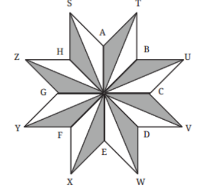
2. Construct the following figure
Solution
The given figure consists of 8 identical rhombuses.
Since,
360° ÷ 8 = 45°
the acute angle between adjacent sides of each rhombus is 45°.
Draw a straight line and mark point A on it.
With A as centre, draw a semicircle.
With B and C as centres, draw arcs of equal radius that meet at D.
Join AD.
Bisect ∠CAD.
With C and E as centres, draw equal arcs meeting at F.
Join AF.
With A as centre, draw an arc intersecting AC and AF at G and H respectively.
With G and H as centres and radius AG, draw arcs meeting at I.
Join the required lines.
AGIH is a rhombus with a base angle of 45°.
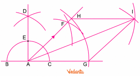
Erase the unnecessary construction lines and arcs.
Colour the upper triangle AHI as shown.
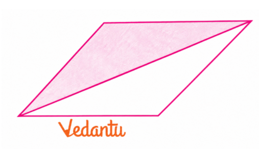
Using tracing paper, make 8 identical copies of this figure.
Arrange all 8 copies together without leaving any gaps.
The required figure is obtained.
Figure It Out
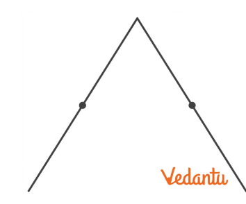
1. Use support lines in Fig. 6.11 to construct a pointed arch. Make
different arches, by changing the radius of the arcs.
Solution
Draw a vertical line B’D’.
With B and B’ as centres, draw arcs of equal radius.
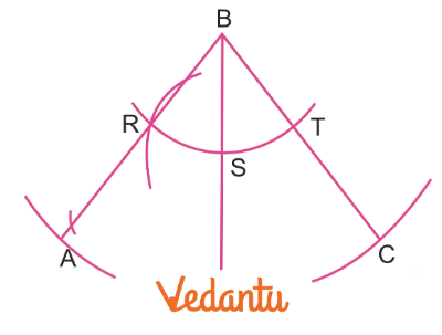
Measure RS using a compass.
Transfer this distance from S’ to locate R’.
R’S’ = RS
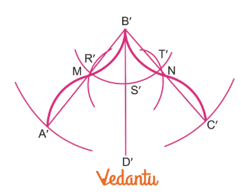
Join B’ and R’ and extend the line.
Mark A’ so that B’A’ = BA.
Measure ST using a compass.
Transfer this distance from S’ to locate T’.
S’T’ = ST
Join B’ and T’ and extend the line.
Mark C’ so that B’C’ = BC.
Using a compass, find the midpoints M and N of A’B’ and B’C’ respectively.
On A’M, MB’, B’N, and NC’, draw similar arcs as shown in the figure.
Erase the unnecessary construction lines, letters, and arcs.
The required pointed arch is obtained.
Different arches can be created by changing the radius of the arcs.
2. Make your own arch design.
Solution
One possible arch design can be constructed as follows:
Draw a vertical line AB.
With A as centre, draw an arc.
With C as centre, draw another arc intersecting the first arc at D and E.
Join AD and AE and extend both lines.
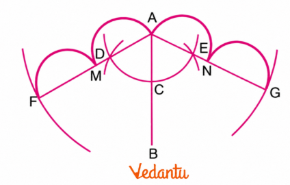
Mark point F on AD and point G on AE so that AF = AG.
Let M and N be the midpoints of AF and AG respectively.
Using a compass, draw semicircles on MF, AM, AN, and NG.
Erase the unnecessary construction lines, letters, and arcs.
The required arch design is obtained.
Figure It Out
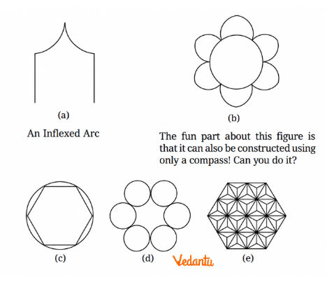
1. Construct the following figures:
Solution
(a)
Draw a straight line and mark points A and B on it.
Using a ruler and compass, construct perpendiculars at A and B below the line.
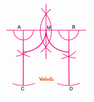
Draw AC and BD of equal length.
AC = BD
Find the midpoint M of AB.
Taking A and B as centres and AM as the radius, draw the required arcs.
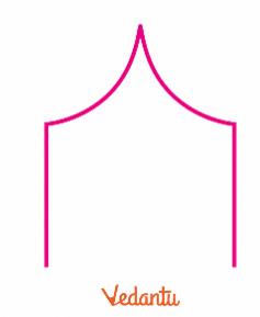
Erase the extra construction lines, arcs, and letters.
The required inflexed arc is obtained.
(b)
This figure is called the ‘Flower of Life’.
Draw a circle. This forms the central circle of the pattern.
Mark any point A on its circumference.
With A as centre and the same radius as the original circle, draw an arc outside the circle that meets the circumference at B and C.
With B as centre and the same radius, draw another arc outside the circle.
Continue the same process around the circle to complete the pattern.
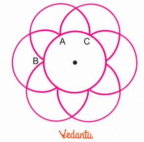
Erase the unnecessary arcs and letters.
The required ‘Flower of Life’ pattern is obtained.

(c)
Draw a circle.
Mark any point A on its circumference.
With A as centre and radius equal to the radius of the circle, draw an arc intersecting the circle at B.
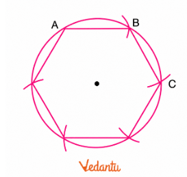
With B as centre and the same radius, draw another arc intersecting the circle at C.
Repeat the same process to obtain points D, E, and F.
Join AB, BC, CD, DE, EF, and FA.
Erase the unnecessary construction arcs and letters.
The required figure is obtained.

(d)
Draw a circle.
Mark any point A on its circumference.
With A as centre and radius equal to the radius of the circle, draw an arc intersecting the circle at B.
With B as centre and the same radius, draw another arc intersecting the circle at C.
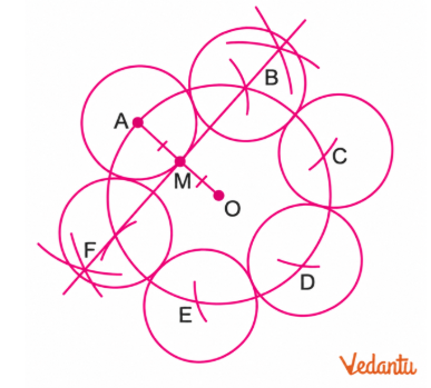
Continue the same process to locate points D, E, and F.
Join O and A.
Find the midpoint M of OA.
With A, B, C, D, E, and F as centres, draw circles of radius OM.
Erase the unnecessary construction lines, arcs, and letters.
The required figure is obtained.

(e)
Draw a circle with centre O.
Mark any point A on the circle.
With A as centre and radius OA, draw an arc intersecting the circle at B.
With B as centre and the same radius, draw another arc intersecting the circle at C.
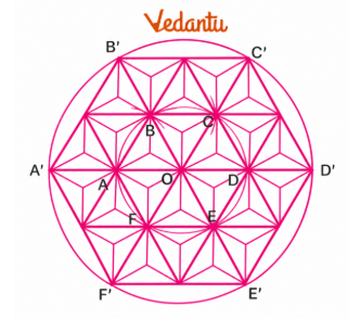
Repeat the same process to obtain points D, E, and F.
Draw another circle with centre O and radius twice OA.
Join OA and extend it until it meets the outer circle at A’.
Similarly, draw the other extended lines.
Join the required points as shown in the figure.
There are 5, 7, 7, and 5 triangles in the first, second, third, and fourth rows respectively.
Join the vertices of each triangle to the centre of that triangle.
Erase the unnecessary construction lines, arcs, and letters.
The required figure is obtained.
2. Optical Illusion: Do you notice anything interesting about the following figure? How does this happen? Recreate this in your notebook.

Solution:
Yes. The figure creates the appearance of a white triangle even though the complete triangle has not actually been drawn.
Draw a circle.
Mark point A at the top of the circle.
With A as centre and radius equal to the radius of the circle, draw an arc intersecting the circle at B.
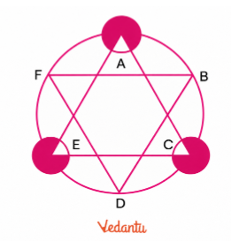
With B as centre and the same radius, draw another arc intersecting the circle at C.
Repeat the process to obtain points D, E, and F.
Join AC, CE, EA, BD, DF, and FB.
Draw three equal circles with wedge-shaped portions removed at A, C, and E, as shown.

Erase the unnecessary arcs, letters, and original circle.
The figure obtained is called the Kanizsa triangle.
The three circles with wedges removed and the three V-shaped angles are arranged in such a way that our brain sees a white equilateral triangle pointing upward, even though no complete triangle is actually drawn.
3. Construct this figure.
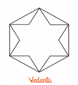
[Hint: Find the angles in this figure.]
Solution
Draw a circle.
Mark point A at the top of the circle.
With A as centre and radius equal to the radius of the circle, draw an arc intersecting the circle at B.
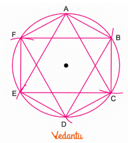
With B as centre and the same radius, draw another arc intersecting the circle at C.
Repeat this process to obtain points D, E, and F.
Join the required points and lines as shown in the given figure.

Erase the unnecessary arcs, original circle, and letters.
The required figure is obtained.
4. Draw a line l and mark a point P anywhere outside the line. Construct a perpendicular to the given line l through P.
[Hint: Find a line segment on l whose perpendicular bisector passes through P.]
Solution:
Draw the given line l and mark point P outside it.
With P as centre, draw an arc large enough to cut line l at two points A and B.
Construct the perpendicular bisector of AB.
With A and B as centres and equal radius, draw arcs above and below AB.
Let these arcs intersect at C and D.
Join C and D and extend the line if required.
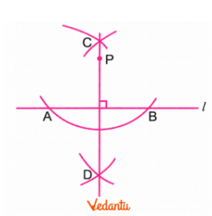
CD is the perpendicular bisector of AB and passes through P.
Therefore,
CD ⟂ l
Hence, CD is the required perpendicular to line l passing through P.
Figure It Out
1. How can the tangram pieces be rearranged to form each of the following figures?
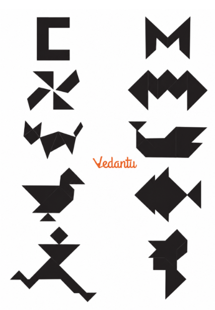
Solution
To solve this, prepare 10 sets of the seven tangram pieces, also called tans, from the given tangram shape.
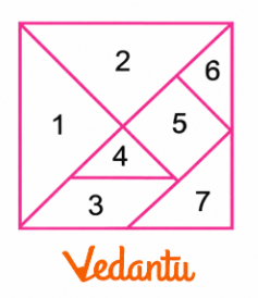
Rearrange the seven tans in different positions and orientations to form each of the required figures. The pieces should fit together without overlapping or leaving unwanted gaps.
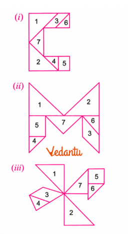
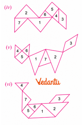
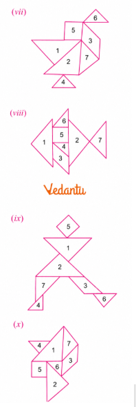
The different arrangements of the same seven tangram pieces form the required figures.
Figure It Out
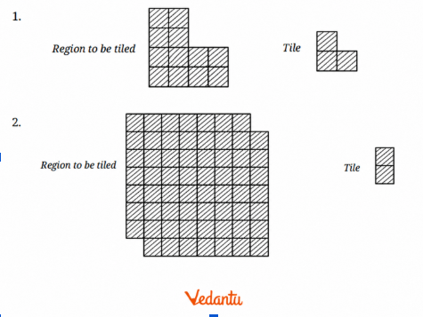
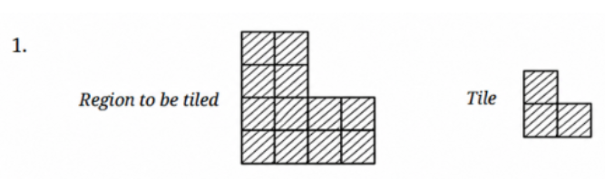
Are the following tiling possible?
Solution
Yes, the tiling is possible.
The region contains 12 unit squares, and each L-shaped tile covers 3 unit squares.
Number of tiles required:
12/3 = 4
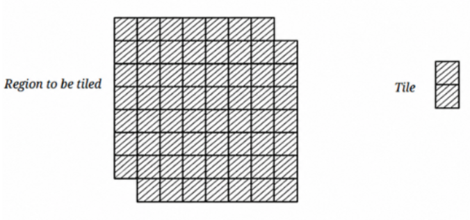
2.
Solution
Although the region contains an even number of unit squares, it cannot be completely covered using the given domino-shaped tile (a tile covering two adjacent squares).
To understand why, imagine colouring the region like a chessboard, using alternating black and white squares. Every domino must cover one black square and one white square.
However, the given region has unequal numbers of black and white squares. Therefore, you cannot tile the entire region without gaps or overlaps.
Key Benefits of Vedantu’s NCERT Solutions for Class 7 Maths Chapter 6 Constructions and Tilings (Ganita Prakash II)
Vedantu’s NCERT solutions for Class 7 Maths Chapter 6 explain construction-based concepts in simple, easy-to-follow steps.
The solutions help students understand why each construction step is performed, rather than simply memorising a procedure.
Students can use the solutions while practising ruler-and-compass constructions and checking whether their construction method is correct.
The solutions explain concepts related to geometric patterns and tilings in a way that helps students improve visualisation and spatial reasoning.
The NCERT solutions for Class 7 Maths Chapter 6 PDF provide a convenient resource for homework support, regular practice and quick revision.
Students can use Vedantu’s solutions alongside the NCERT textbook to strengthen their understanding of geometry and build confidence when solving construction-based questions.
Important Study Material Links for Chapter 6: Constructions and Tilings
NCERT Solutions for Class 7 Maths Ganita Prakash I and II (New Syllabus)
Important Related Links for NCERT Class 7 Maths
FAQs on NCERT Solutions for Class 7 Maths Chapter 6 Constructions and Tilings | 2026-27
1. What do students learn in NCERT Class 7 Maths Chapter 6 (Ganita Prakash II) Constructions and Tilings?
Chapter 6 helps students understand geometric constructions and tiling patterns. It introduces tools such as a ruler and compass, accurate drawing methods, geometric relationships, and how different shapes fit together without gaps or overlaps.
2. Where can students find NCERT Solutions for Class 7 Maths Chapter 6?
Students can refer to Vedantu’s NCERT Solutions for Class 7 Maths Chapter 6 for clear, step-by-step explanations of the textbook concepts and construction-based questions. The solutions help students understand both the method and the reasoning behind each construction.
3. How can CBSE NCERT Solutions for Class 7 Maths Chapter 6 help with construction questions?
The CBSE NCERT Solutions for Class 7 Maths Chapter 6 help students follow the correct sequence of construction steps, use geometric tools accurately, and identify mistakes in their diagrams. This is especially useful for questions where precision and the correct method are important.
4. What is the best way to practise Chapter 6 Constructions and Tilings?
Students should practise each construction directly with a ruler, compass and pencil instead of only reading the steps. After attempting a question, they can compare their method with the NCERT Maths Solutions for Class 7 Chapter 6 and correct any errors in measurement, arcs or point placement.
5. Is the NCERT Solutions for Class 7 Maths Chapter 6 PDF useful for revision?
Yes. The NCERT Solutions for Class 7 Maths Chapter 6 PDF helps you revise key construction methods, textbook solutions, and chapter concepts in one place. It can also help students quickly review difficult questions before school tests and examinations.
6. What should students focus on while preparing Class 7 Maths Chapter 6 for exams?
Students should focus on understanding the logic behind each construction step, using a compass and ruler correctly, drawing neat and accurate figures, and recognising how shapes form tiling patterns. Students can then use the NCERT Solutions for Class 7 Chapter 6 Maths to check the correct method and revise important textbook questions.