


How Do Resistors Affect Current in a Circuit?
Resistors and resistance are fundamental concepts in the study of electrical circuits. They describe both the components that limit the flow of electric current and the quantitative property that measures this opposition. Understanding these concepts is essential for analyzing and designing a wide range of electrical and electronic circuits.
Definition of Resistance and Resistors
Resistance is the property of a material or component that opposes the flow of electric current. It is denoted by the symbol $R$ and measured in ohms $(\Omega)$. High resistance reduces current, while low resistance allows more current to pass.
A resistor is a passive electrical component specifically designed to provide a fixed or variable resistance within a circuit. Resistors are used to control current, divide voltage, and protect sensitive components. For an in-depth overview, refer to the In-Depth on Resistors and Resistance.
Ohm’s Law and Its Application
Ohm’s Law is a fundamental relationship in electrical circuits, establishing a linear connection between voltage $(V)$, current $(I)$, and resistance $(R)$. It is valid for ohmic materials under constant temperature and physical conditions.
The law is given by the equation $V = IR$. This can be rearranged as $I = \dfrac{V}{R}$ and $R = \dfrac{V}{I}$ as per the required parameter.
Electric power dissipated in a resistor is calculated as $P = VI$, which can also be written as $P = \dfrac{V^2}{R} = I^2R$ using Ohm’s Law. For more detailed explanations, visit Ohm's Law and Resistance.
Types of Resistors
Resistors can be categorized as fixed or variable based on whether their resistance value is constant or adjustable. Fixed resistors include carbon composition, metal film, and wire wound types. Variable resistors, such as potentiometers and rheostats, allow resistance adjustment as needed in a circuit.
Resistors in Series
When resistors are connected end-to-end, they form a series connection. The current flowing through each resistor is the same, but the total voltage is divided among the individual resistors. This arrangement increases the overall resistance in the circuit.

The equivalent resistance for $n$ resistors $R_1, R_2, ..., R_n$ connected in series is given by:
$R_{\text{eq}} = R_1 + R_2 + \dots + R_n$
A series arrangement is used when a higher total resistance or voltage division is required. Additional examples and techniques can be explored in the Circuit Solving Techniques section.
Resistors in Parallel
In a parallel connection, resistors are connected such that both ends of each resistor are attached to the same nodes. This creates multiple paths for current, with each resistor experiencing the same potential difference.
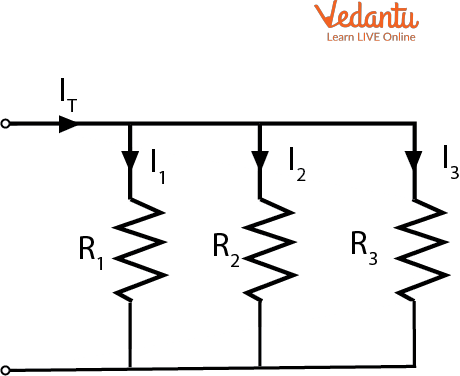
The reciprocal of the equivalent resistance for $n$ resistors in parallel is:
$\dfrac{1}{R_{\text{eq}}} = \dfrac{1}{R_1} + \dfrac{1}{R_2} + \dots + \dfrac{1}{R_n}$
Parallel connections are used to decrease the overall resistance and distribute current. Repairs or failures do not interrupt the entire circuit. Additional principles are available in the Exploring Electrical Resistance page.
Comparison: Series and Parallel
| Aspect | Series |
|---|---|
| Current | Same through all resistors |
| Voltage | Divided across resistors |
| Equivalent Resistance | Higher than any individual resistor |
| Aspect | Parallel |
|---|---|
| Current | Divided among resistors |
| Voltage | Same across all resistors |
| Equivalent Resistance | Lower than the smallest individual resistor |
Factors Affecting Resistance
The resistance of a conductor depends on several factors including length $(l)$, cross-sectional area $(A)$, material type, and temperature. The relation is given by $R = \rho\dfrac{l}{A}$, where $\rho$ is the resistivity of the material.
Materials with low resistivity, like copper and aluminum, are used for conducting wires. Those with high resistivity are used to manufacture resistors. An extended discussion is provided in the Guide to Resistance.
Resistors, Circuits, and Current
Resistors play a crucial role in controlling the magnitude of current in circuits according to $I = \dfrac{V}{R}$. By choosing suitable resistor values and arrangements, the desired current and voltage values can be achieved in different branches of a circuit.
Resistors are fundamental elements in both simple and complex circuits, impacting performance and safety. For topics involving both resistors and capacitors, see Understanding RC Circuits.
Difference Between Resistors and Resistance
| Resistor | Resistance |
|---|---|
| Physical component in circuits | Property of materials or devices |
| Manufactured as fixed or variable types | Measured in ohms $(\Omega)$ |
| Controls current and voltage | Numerical measure of opposition to current |
Solved Example: Calculating Equivalent Resistance
Three resistors of $4\ \Omega$, $6\ \Omega$, and $12\ \Omega$ are connected in parallel. Find the equivalent resistance.
Using the parallel formula:
$\dfrac{1}{R_{\text{eq}}} = \dfrac{1}{4} + \dfrac{1}{6} + \dfrac{1}{12} = \dfrac{3 + 2 + 1}{12} = \dfrac{6}{12} = \dfrac{1}{2}$
$R_{\text{eq}} = 2\ \Omega$
Summary of Key Points
- Resistance opposes the flow of electric current
- Resistors control current and voltage
- Ohm’s Law links voltage, current, and resistance
- Series connection increases total resistance
- Parallel connection decreases total resistance
- Material, length, area, and temperature affect resistance
FAQs on Understanding Resistors and Electrical Resistance
1. What is resistance in a resistor?
Resistance is the property of a resistor that opposes the flow of electric current through it.
Key points:
- The SI unit of resistance is ohm (Ω).
- It controls how much current flows for a given voltage, as described by Ohm’s Law.
- Higher resistance means less current flows through the circuit.
2. State Ohm’s Law and its mathematical expression.
Ohm's Law states that the current (I) flowing through a conductor between two points is directly proportional to the potential difference (V) across the two points, provided the temperature remains constant.
- Mathematically: V = IR
- V = voltage across resistor
- I = current through resistor
- R = resistance of resistor
3. What factors affect the resistance of a conductor?
The resistance of a conductor depends on several key factors:
- Length (l): Longer conductors have higher resistance.
- Cross-sectional area (A): Thicker conductors (larger area) have lower resistance.
- Material: Materials with higher resistivity offer greater resistance.
- Temperature: Most metals increase in resistance as temperature increases.
4. What is the SI unit of resistance?
The standard SI unit for measuring resistance is the ohm (Ω).
- 1 ohm is defined as the resistance that allows a current of 1 ampere to flow when a voltage of 1 volt is applied across it.
5. Define resistivity. How does it differ from resistance?
Resistivity is an intrinsic property of a material that indicates how much it resists current flow, regardless of its shape or size.
- Resistivity is denoted by the Greek letter ρ (rho).
- Its SI unit is ohm-metre (Ω·m).
- Resistance depends on length and area, while resistivity depends only on material type and temperature.
6. How does resistance change with temperature?
For most metals, resistance increases as temperature increases.
- Metals: Resistance increases due to more frequent collisions among electrons.
- Semi-conductors: Resistance usually decreases with rise in temperature.
7. What is the formula for the resistance of a uniform wire?
The resistance R of a uniform wire is given by the formula:
R = ρ (l / A)
- R = resistance (ohms)
- ρ = resistivity of the material (ohm-metre)
- l = length of the wire (metres)
- A = cross-sectional area of the wire (square metres)
8. What happens to the total resistance if resistors are connected in series?
When resistors are connected in series, their total or equivalent resistance increases, calculated as the sum of individual resistances.
- RTotal = R1 + R2 + R3 + ...
9. Compare resistance in series and parallel connections of resistors.
The way resistors are connected affects the total resistance in a circuit:
- Series connection: Resistance adds up (RT = R1 + R2 + ...)
- Parallel connection: The reciprocal of total resistance is the sum of reciprocals (1/RT = 1/R1 + 1/R2 + ...), so resistance decreases.
10. Describe practical applications of resistors in electric circuits.
Resistors have several important uses in electric circuits and electronic devices:
- Limit the flow of electric current
- Divide voltage within circuits (voltage divider)
- Protect sensitive components
- Generate heat in devices like heaters and toasters
11. Why are alloys like nichrome used as resistive materials?
Alloys such as nichrome are used for making resistive elements because they have high resistivity and do not oxidise easily at high temperatures.
- Remain stable and durable during heating
- Used in electric heaters, toasters, and scientific instruments