


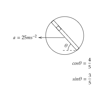
A circular disc with a groove along its diameter is placed horizontally. A block of mass $1{\text{kg}}$ is placed as shown. The coefficient of friction between the block and all the surfaces of the groove in contact is $\mu = \dfrac{2}{5}$ . The disc has an acceleration of $25{\text{m}}{{\text{s}}^{ - 2}}$ . Find the acceleration of the block with respect to the disc.
Answer
233.1k+ views
Hint: Here as the disc moves to the left, the block inside the groove will move downwards and upwards causing the groove to turn and the angle $\theta $ changes accordingly. As the block slides, both of its sides are in contact with the surface of the groove which results in two frictional forces and two normal forces corresponding to each side. The pseudo force will make the angle $\theta $ with the horizontal direction and will be towards right as the disc moves towards left. Sketching a free body diagram of the system will provide a better understanding
Formulas used:
The frictional force acting on a body is given by, $f = \mu N$ where $\mu $ is the coefficient of friction and $N$ is the normal force acting on the body.
The force acting on a body is given by, $F = ma$ where $m$ is the mass of the body and $a$ is its acceleration.
Complete step by step solution:
Step 1: Sketch a free body diagram of the given system. Also, list the given parameters.
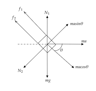
The above figure is the free body diagram of the system involving a disc with a groove along its diameter onto which a block is placed.
The above figure depicts the direction of the forces in play.
The mass of the block is given to be $m = 1{\text{kg}}$ .
The coefficient of frictional force is given to be $\mu = \dfrac{2}{5}$ and the acceleration of the disc is $a = 25{\text{m}}{{\text{s}}^{ - 2}}$ .
It is also given that $\cos \theta = \dfrac{4}{5}$ and $\sin \theta = \dfrac{3}{5}$ .
Let ${a_b}$ be the acceleration of the block which is to be determined.
Here the two frictional forces corresponding to the two points of contact are marked as ${f_1}$ and ${f_2}$ . The normal forces acting on either side of the block are marked as ${N_1}$ and ${N_2}$ .
The pseudo force acting on the block due to the acceleration of the disc to the right is given by $F = ma$ and it makes the angle $\theta $ with the block. The cosine component and the sine component of the force are given as $ma\cos \theta $ and $ma\sin \theta $ .
The weight of the block $W = mg$ is directed downwards.
Step 2: Express the force balance equation in all directions.
From the figure, we see that the weight of the body $W = mg$ is balanced by the normal force ${N_1}$ .
i.e., ${N_1} = mg$ --------- (1)
From the figure, we also see that the sine component of the force $ma\sin \theta $ is balanced by the normal force ${N_2}$ .
i.e., ${N_2} = ma\sin \theta $ ----------- (2)
As the block is directed along the cosine component of the force, the net force acting on the block can be expressed as $ma\cos \theta - {f_1} - {f_2} = m{a_b}$
Since the frictional forces can be expressed as ${f_1} = \mu {N_1}$ and ${f_2} = \mu {N_2}$ the above equation becomes $ma\cos \theta - \mu {N_1} - \mu {N_2} = m{a_b}$ ---------- (3)
Substituting equations (1) and (2) in (3) we get, $ma\cos \theta - \mu mg - \mu ma\sin \theta = m{a_b}$
$ \Rightarrow {a_b} = a\cos \theta - \mu g - \mu a\sin \theta $ ------- (4)
Step 3: Substitute values in equation (4) to find the acceleration of the block.
Substituting for $a = 25{\text{m}}{{\text{s}}^{ - 2}}$ , $\mu = \dfrac{2}{5}$, $\cos \theta = \dfrac{4}{5}$, $\sin \theta = \dfrac{3}{5}$ and $g = 10{\text{m}}{{\text{s}}^{ - 2}}$ in equation (4) we get, ${a_b} = \left( {25 \times \dfrac{4}{5}} \right) - \left( {\dfrac{2}{5} \times 10} \right) - \left( {\dfrac{2}{5} \times 25 \times \dfrac{3}{5}} \right)$
Calculating this becomes ${a_b} = 20 - 4 - 6 = 10{\text{m}}{{\text{s}}^{ - 2}}$.
Thus the acceleration of the block is ${a_b} = 10{\text{m}}{{\text{s}}^{ - 2}}$.
Note: When the disc moves towards left with the given acceleration, the block will slide down and the angle $\theta $ will increase as the groove turns in the anticlockwise direction. The angle will increase until the groove turns to a maximum and will then decrease as the groove returns to its initial position. We consider the pseudo force because the block is in a non-inertial frame of reference.
Formulas used:
The frictional force acting on a body is given by, $f = \mu N$ where $\mu $ is the coefficient of friction and $N$ is the normal force acting on the body.
The force acting on a body is given by, $F = ma$ where $m$ is the mass of the body and $a$ is its acceleration.
Complete step by step solution:
Step 1: Sketch a free body diagram of the given system. Also, list the given parameters.
The above figure is the free body diagram of the system involving a disc with a groove along its diameter onto which a block is placed.
The above figure depicts the direction of the forces in play.
The mass of the block is given to be $m = 1{\text{kg}}$ .
The coefficient of frictional force is given to be $\mu = \dfrac{2}{5}$ and the acceleration of the disc is $a = 25{\text{m}}{{\text{s}}^{ - 2}}$ .
It is also given that $\cos \theta = \dfrac{4}{5}$ and $\sin \theta = \dfrac{3}{5}$ .
Let ${a_b}$ be the acceleration of the block which is to be determined.
Here the two frictional forces corresponding to the two points of contact are marked as ${f_1}$ and ${f_2}$ . The normal forces acting on either side of the block are marked as ${N_1}$ and ${N_2}$ .
The pseudo force acting on the block due to the acceleration of the disc to the right is given by $F = ma$ and it makes the angle $\theta $ with the block. The cosine component and the sine component of the force are given as $ma\cos \theta $ and $ma\sin \theta $ .
The weight of the block $W = mg$ is directed downwards.
Step 2: Express the force balance equation in all directions.
From the figure, we see that the weight of the body $W = mg$ is balanced by the normal force ${N_1}$ .
i.e., ${N_1} = mg$ --------- (1)
From the figure, we also see that the sine component of the force $ma\sin \theta $ is balanced by the normal force ${N_2}$ .
i.e., ${N_2} = ma\sin \theta $ ----------- (2)
As the block is directed along the cosine component of the force, the net force acting on the block can be expressed as $ma\cos \theta - {f_1} - {f_2} = m{a_b}$
Since the frictional forces can be expressed as ${f_1} = \mu {N_1}$ and ${f_2} = \mu {N_2}$ the above equation becomes $ma\cos \theta - \mu {N_1} - \mu {N_2} = m{a_b}$ ---------- (3)
Substituting equations (1) and (2) in (3) we get, $ma\cos \theta - \mu mg - \mu ma\sin \theta = m{a_b}$
$ \Rightarrow {a_b} = a\cos \theta - \mu g - \mu a\sin \theta $ ------- (4)
Step 3: Substitute values in equation (4) to find the acceleration of the block.
Substituting for $a = 25{\text{m}}{{\text{s}}^{ - 2}}$ , $\mu = \dfrac{2}{5}$, $\cos \theta = \dfrac{4}{5}$, $\sin \theta = \dfrac{3}{5}$ and $g = 10{\text{m}}{{\text{s}}^{ - 2}}$ in equation (4) we get, ${a_b} = \left( {25 \times \dfrac{4}{5}} \right) - \left( {\dfrac{2}{5} \times 10} \right) - \left( {\dfrac{2}{5} \times 25 \times \dfrac{3}{5}} \right)$
Calculating this becomes ${a_b} = 20 - 4 - 6 = 10{\text{m}}{{\text{s}}^{ - 2}}$.
Thus the acceleration of the block is ${a_b} = 10{\text{m}}{{\text{s}}^{ - 2}}$.
Note: When the disc moves towards left with the given acceleration, the block will slide down and the angle $\theta $ will increase as the groove turns in the anticlockwise direction. The angle will increase until the groove turns to a maximum and will then decrease as the groove returns to its initial position. We consider the pseudo force because the block is in a non-inertial frame of reference.
Recently Updated Pages
JEE Main 2023 April 6 Shift 1 Question Paper with Answer Key
JEE Main 2023 April 6 Shift 2 Question Paper with Answer Key
JEE Main 2023 (January 31 Evening Shift) Question Paper with Solutions [PDF]
JEE Main 2023 January 30 Shift 2 Question Paper with Answer Key
JEE Main 2023 January 25 Shift 1 Question Paper with Answer Key
JEE Main 2023 January 24 Shift 2 Question Paper with Answer Key
Trending doubts
JEE Main 2026: Session 2 Registration Open, City Intimation Slip, Exam Dates, Syllabus & Eligibility
JEE Main 2026 Application Login: Direct Link, Registration, Form Fill, and Steps
Understanding the Angle of Deviation in a Prism
Hybridisation in Chemistry – Concept, Types & Applications
How to Convert a Galvanometer into an Ammeter or Voltmeter
Understanding Uniform Acceleration in Physics
Other Pages
JEE Advanced Marks vs Ranks 2025: Understanding Category-wise Qualifying Marks and Previous Year Cut-offs
Laws of Motion Class 11 Physics Chapter 4 CBSE Notes - 2025-26
Waves Class 11 Physics Chapter 14 CBSE Notes - 2025-26
Mechanical Properties of Fluids Class 11 Physics Chapter 9 CBSE Notes - 2025-26
Thermodynamics Class 11 Physics Chapter 11 CBSE Notes - 2025-26
Units And Measurements Class 11 Physics Chapter 1 CBSE Notes - 2025-26