


An Overview of Class 10 Physics Lab Manual Determination Of The Equivalent Resistance Of Resistors When Connected In Series
Physics-Experiment - Determination of the Equivalent Resistance of Resistors When Connected in Series - Introduction
When two resistors are connected in an end-to-end manner in a circuit then they are considered to be connected in the series. In a series combination, the flow of current is the same in both resistors, since the current always flows in one direction; however, the total voltage of the battery drops across the resistors depending on the value of their resistances. Therefore, in the household, the appliances connected in series sometimes fail due to the flow of an unexpectedly high current through the circuit and causing short circuits.
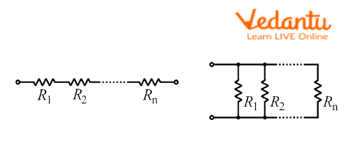
Series and Parallel combination of resistors
Table of Content
(a) Physics-Experiment - Determination of the Equivalent Resistance of Resistors When Connected in Series - Introduction
Aim
Theory
Procedure
Observations
Result
(b) To Determine the Equivalent Resistance of Resistors When Connected in Parallel
Introduction
Aim
Theory
Observations
Result
Precautions
Aim
Determination of equivalent resistance in a series combination of resistances.
Apparatus Required
List of tools required to experiment:
Connecting wires
A 12 V Battery
A plug key
A Rheostat
An ammeter
A voltmeter
A piece of sandpaper
Two resistors of different values
Rheostat
Theory
The resistances connected in the series combination will have an equal amount of current; and the total voltage drop across the resistor will depend on the effective resistance of that resistor. Let's consider that there are two resistances of values \[{R_1}\;and\;{R_2}\] connected in a series combination. When a current of value \[I\] flows through this resistance, a voltage drop \[{V_1}\;and\;{V_2}\] occurs across them. Since the total voltage of the battery \[V\]is fixed, therefore, we can write,
\[V = {V_1} + {V_2}\]
According to Ohm’s law, the voltage drop across each resistor can be given as follows,
\[\begin{array}{l}{V_1} = I{R_1}\\{V_2} = I{R_2}\end{array}\]
Now substitute these values in the above expression, and we get,
\[V = I{R_1} + I{R_2}\]
Now, if we consider that the equivalent resistance of the circuit is \[R\], then the total voltage drop will be, \[V = IR\], and thus we can write the above expression as,
\[\begin{array}{l}V = IR = I{R_1} + I{R_2}\\R = {R_1} + {R_2}\end{array}\]
Thus, the equivalent resistance of a series circuit can be expressed as,
\[R = {R_1} + {R_2}\]
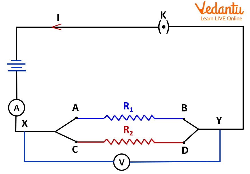
Procedure
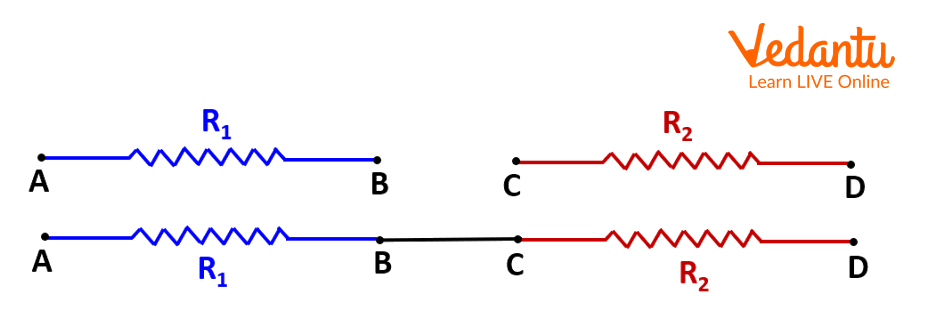
Series combination of resistors.
Circuit for series combination of two resistors AB and CD.
Please follow these steps one by one:
Make sure to check the zeros of the Ammeter and Voltmeters and note down the least counts of them.
Clean the joining ends of the connecting wire to make sure the proper electric connections.
Do not insert the plug key.
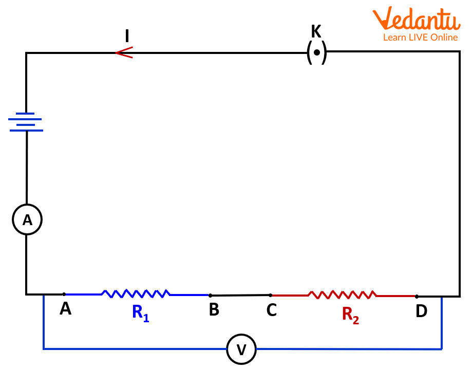
Take two resistors of known resistance and connect them in a circuit as given in the image 2 and connect the other components, like, ammeter, voltmeter, key, battery, and others systematically.
Connect the two known resistors with a connecting wire at the ends B and C as shown in the Image 2.
Now, Insert the plug key in the circuit to allow the flow of current in the circuit and note down the readings of the ammeter and voltmeter across the A and D points of the circuit as shown in Image 2. Now, remove the plug key to avoid the excessive heating of the wires.
Repeat this experiment with the five different values of currents and note down the readings of a voltmeter and an ammeter in each case as recorded in the step 5 above.
Observations
Least Count of Ammeter = …. A
Range of Ammeter = …. A
Least Count of Voltmeter = …. V
Range of Voltmeter = …. V
Resistance of the first resistor = ….Ω
Resistance of the second resistor = ….Ω
Resistance of the first resistor = ….Ω
Resistance of the second resistor = ….Ω
Equivalent Resistance = ….Ω
Result
Now compare the experimentally obtained value of equivalent resistance with the calculated value of the equivalent resistance from the above equation. Write your observation here ____.
(b) To Determine the Equivalent Resistance of Resistors When Connected in Parallel
Introduction
When resistors are connected across each other in a circuit, then those resistors are considered to be connected in a parallel combination. In a parallel combination, the current flow is divided among the resistors, while the voltage drop across each resistor is the same, depending on the value of these individual resistors. Therefore, in the household wiring, all electric appliances are connected in a parallel combination to ensure an equal voltage to each of them, and, therefore, the undisturbed operation is maintained.
Parallel combination of resistors
Aim
Determination of equivalent resistance in a parallel combination of resistors.
Apparatus Required
List of tools required to perform the experiment:
Connecting wires
A 12 V Battery
A plug key
A Rheostat
An ammeter
A voltmeter
A piece of sandpaper
Two resistors of different values
Rheostat
Theory
The resistors are connected in a parallel combination and will encounter an equal amount of voltage drop across each of them and the current will be divided among these resistors depending on their value. If we consider that the two resistors of values \[{R_1}\; and\;{R_2}\] are connected in a parallel combination, and both experience a voltage drop \[V\], when the current \[{i_1}\; and\;{i_2}\] flows through these resistors, respectively. Since the total current from the battery \[i\] is fixed, therefore, we can write,
\[i = {i_1} + {i_2}\]

Circuit diagram for the Parallel combination.
According to Ohm’s law, the voltage drop across each resistor can be given as follows,
\[\begin{array}{l}{i_1} = \dfrac{V}{{{R_1}}}\\{i_2} = \dfrac{V}{{{R_2}}}\end{array}\]
Now substitute these values in the above expression, and we get,
\[i = \dfrac{V}{{{R_1}}} + \dfrac{V}{{{R_2}}}\]
Now, if we consider that the equivalent resistance of the circuit is \[R\], then the total voltage drop will be, \[V = IR\], and thus we can write the above expression as,
\[\begin{array}{l}\dfrac{V}{R} = \dfrac{V}{{{R_1}}} + \dfrac{V}{{{R_2}}}\\\dfrac{1}{R} = \dfrac{1}{{{R_1}}} + \dfrac{1}{{{R_2}}}\end{array}\]
Thus, the equivalent resistance of a series circuit can be expressed as,
\[\dfrac{1}{R} = \dfrac{1}{{{R_1}}} + \dfrac{1}{{{R_2}}}\]
Procedure
Please follow these steps one by one:
Make sure to check the zeros of the Ammeter and Voltmeters and note down the least counts of them.
Clean the joining ends of the connecting wire to ensure the proper electric connections.
Do not insert the plug key.
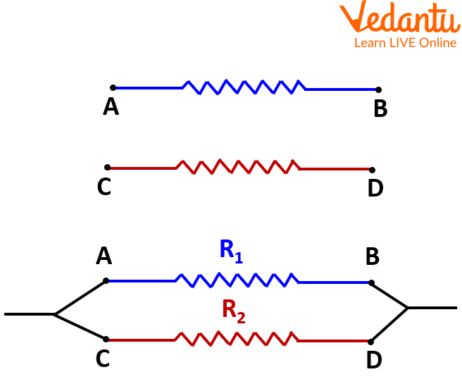
Take two resistors of known resistance and connect them in a circuit as given in image 4 and connect the other components, like, the ammeter, voltmeter, key, battery, and others systematically.
Connect the two known resistors with a connecting wire at the ends A and C as well as B and D, as shown in the image 4.
Now, insert the plug key in the circuit to allow the flow of current in the circuit and note down the readings of the ammeter and voltmeter across the X and Y points of the circuit as shown in image 2. Now, remove the plug key to avoid the excessive heating of the wires.
Repeat this experiment with the five different values of currents and note down the readings of the voltmeter and an ammeter in each case as recorded in the step 5 above.
Observations
Least Count of Ammeter = …. A
Range of Ammeter = …. A
Least Count of Voltmeter = …. V
Range of Voltmeter = …. V
Resistance of the first resistor = ….Ω
Resistance of the second resistor = ….Ω
Resistance of the first resistor = ….Ω
Resistance of the second resistor = ….Ω
Equivalent Resistance = ….Ω
Result
Now, compare the experimentally obtained value of equivalent resistance with the calculated value of the equivalent resistance from the above equation. Write your observation here____.
Precautions
Please make sure that the connections are tight.
Insert and remove the plug key as mentioned in the procedure.
The voltmeter should always be connected parallel to the resistors.
The ammeter should always be connected in series with the resistors.
The least count of the voltmeter and ammeter should be determined properly.
All connections should be made following the diagram.
To avoid Joule heating, the current should flow when recording the readings.
Lab Manual Questions
In what way should household appliances be connected??
Ans: In the household circuits to supply the equivalent voltage to each appliance, they are connected in a parallel combination. In addition, it ensures that the working of other electric appliances will remain unaffected if there is some issue with the other appliances.
Two resistors are connected in series and then in parallel. What effect will it have on the readings of the voltmeter and ammeter?
Ans: Two resistors in a series combination will result in the same value of current and different readings of voltages when an ammeter and voltmeters are connected across them, respectively, while two resistors connected in parallel will give the same readings in a voltmeter and different readings in the ammeter when connected across them, respectively.
What will be the equivalent resistance for the \[5\;\Omega \;and\;10\;\Omega \] connected in parallel?
Ans: The equivalent resistance can be calculated as follows for the \[5\;\Omega \;and\;10\;\Omega \] resistors connected in parallel such that,
\[\begin{array}{l}\dfrac{1}{{{R_P}}} = \dfrac{1}{{5\;\Omega }} + \;\dfrac{1}{{10\;\Omega}}\\\dfrac{1}{{{R_P}}} = \dfrac{{2 + 1}}{{10\;\Omega }}\\{R_P} = \dfrac{{10}}{3}\;\Omega \end{array}\]
Thus, the equivalent resistance is \[{R_P} = \dfrac{{10}}{3}\;\Omega \].
What will be the equivalent resistance for the \[5\;\Omega \;and\;10\;\Omega \] connected in series?
Ans: The equivalent resistance can be calculated as follows for the \[5\;\Omega \;and\;10\;\Omega \] resistors connected in series such that,
\[\begin{array}{l}{R_S} = 5\;\Omega + \;10\;\Omega \\{R_S} = 15\;\Omega \end{array}\]
Thus, the equivalent resistance is \[{R_S} = 15\;\Omega \].
Viva Questions
1. What is a voltmeter?
Ans: Voltmeter is an electric device utilized to measure the voltage across the electric component when connected parallel to it.
2. What is an ammeter?
Ans: An ammeter is an electric device utilized to measure the current flow along an electric component when connected in series to it.
3. What is the use of a rheostat?
Ans: The rheostat is used as a device of variable resistance in an electric circuit.
4. Name some wire materials that can be used for making electric connections?
Ans: Copper, Aluminium, Silver, Gold, etc.
5. What is Ohm’s law?
Ans: Ohm’s law states that the voltage is directly proportional to the electric current in the circuit; therefore, \[V = IR\].
6. What will happen to voltage if the current through a resistor is increased in a circuit?
Ans: Since voltage is directly proportional to the current, therefore voltage will also increase with the current.
7. Why is the ammeter connected in the series?
Ans: The ammeter is connected in series; therefore, the same current flows through the ammeter and measures the same value of current passing through the electric circuit.
8. Why is the voltmeter connected to a parallel?
Ans: The voltmeter is connected to a parallel since it measures the total voltage drop across the electric component.
9. How can an ammeter be formed using a galvanometer?
Ans: An ammeter can be formed using a galvanometer if a resistance of a smaller value is connected parallel to it, so the total resistance will be very low and that makes it suitable to flow the current.
10. How can a voltmeter be formed using a galvanometer?
Ans: A voltmeter can be formed using a galvanometer if a resistance of a large value is connected in series to it, so the total resistance will be very high and that makes it suitable that there will be no leakage of current through it and drops the maximum voltage.
Practical-Based Resistors in Series and Parallel Problems and Solutions
1. When resistors are connected in series, what happens to the final resistance?
Decrease
Increase
No change
Infinite
Ans: B. Increase
2. Where should a voltmeter be connected in a circuit?
Parallel
Series
Between two resistors
Across switch
Ans: A. Parallel
3. Where should an ammeter be connected in a circuit?
Parallel
Series
Between two resistors
Across switch
Ans: B. Series
4. What will be the voltmeter reading across a \[2\;\Omega \] resistor that has a 1 A current?
2 V
0.5 V
10 V
1.2 V
Ans: A. 2 V
5. When resistors are connected in parallel, what happens to the final resistance?
Decrease
Increase
No change
Infinite
Ans: A. Decrease
6. What is the unit of voltage?
\[\Omega \]
unitless
V
A
Ans: C. V
7. What is the unit of current?
\[\Omega \]
unitless
V
A
Ans: D. A
8. What is the unit of resistance?
\[\Omega \]
unitless
V
A
Ans: A. \[\Omega \]
9. What is the use of a key in an electric circuit?
Connect the circuit
Disconnect the circuit
Increase Current
Decrease Current
Ans: A. Connect the circuit
10. Which formula is used for the equivalent resistance of two resistors in series?
\[\dfrac{1}{{{R_1}}} + \dfrac{1}{{{R_2}}}\]
\[{R_1} + {R_2}\]
\[{R_1} - {R_2}\]
\[{R_1}/{R_2}\]
Ans: B. \[{R_1} + {R_2}\]
Conclusion
From this experiment, one can conclude that the combination of resistors in parallel or series combination decreases and increases, respectively. In the series combination, the voltage is divided among resistors, and the same current flows through the resistors. In a parallel combination, current divides among the resistors, and the voltage remains the same. Therefore, a desired value of the resistance can be obtained from a series of parallel combinations of resistors.


FAQs on Class 10 Physics Lab Manual Determination Of The Equivalent Resistance Of Resistors When Connected In Series
1. What are the key differences between series and parallel combinations of resistors, which are important for the CBSE Class 10 Board Exam 2025-26?
The most important differences to remember for your exams are:
- Current Flow: In a series combination, the same current flows through every resistor. In a parallel combination, the current divides among the different branches.
- Voltage Distribution: In a series circuit, the total voltage is divided among the resistors. In a parallel circuit, the voltage across each resistor is the same.
- Equivalent Resistance: The equivalent resistance in a series circuit is the sum of individual resistances (Rs = R1 + R2 + ...) and is always greater than the largest individual resistance. In a parallel circuit, the reciprocal of the equivalent resistance is the sum of the reciprocals of individual resistances (1/Rp = 1/R1 + 1/R2 + ...) and is always less than the smallest individual resistance.
- Effect of a Fault: If one component fails in a series circuit, the entire circuit breaks. In a parallel circuit, other branches continue to function even if one fails.
2. Derive the expression for the equivalent resistance of three resistors (R₁, R₂, and R₃) connected in series.
This is a frequently asked 3-mark question. Here is the step-by-step derivation:
When resistors are connected in series, the current (I) flowing through each resistor is the same. The total potential difference (V) across the combination is the sum of the potential differences across each resistor (V₁, V₂, V₃).
- Total Voltage, V = V₁ + V₂ + V₃
- According to Ohm's Law, V = IR. Applying this to each resistor: V₁ = IR₁, V₂ = IR₂, and V₃ = IR₃.
- Let Rs be the equivalent resistance of the series circuit. The total voltage is V = IRs.
- Substituting these values into the first equation: IRs = IR₁ + IR₂ + IR₃
- Factoring out the common term I: IRs = I(R₁ + R₂ + R₃)
- Cancelling I from both sides, we get the final expression: Rs = R₁ + R₂ + R₃.
3. A 4 Ω resistor and a 6 Ω resistor are connected in parallel. This combination is then connected in series with an 8 Ω resistor and a 12V battery. What is the total equivalent resistance of the circuit?
This is a typical 3-mark numerical problem. To solve this, we break it down into steps:
Step 1: Calculate the equivalent resistance of the parallel combination.
- Let Rp be the equivalent resistance for the 4 Ω and 6 Ω resistors in parallel.
- The formula is 1/Rp = 1/R₁ + 1/R₂.
- 1/Rp = 1/4 + 1/6 = (3 + 2) / 12 = 5/12
- Therefore, Rp = 12/5 = 2.4 Ω.
Step 2: Calculate the total equivalent resistance of the entire circuit.
- The parallel combination (Rp) is connected in series with the 8 Ω resistor.
- The total equivalent resistance (Rtotal) is the sum of Rp and the series resistor.
- Rtotal = Rp + 8 Ω = 2.4 Ω + 8 Ω = 10.4 Ω.
The total equivalent resistance of the circuit is 10.4 Ω.
4. Why are domestic electrical appliances connected in parallel and not in series? State two important reasons.
This is a high-order thinking skill (HOTS) question often asked in board exams. Domestic appliances are connected in a parallel combination for these crucial reasons:
- Independent Operation: In a parallel circuit, each appliance has its own switch and can be turned on or off independently without affecting other appliances. If they were in series, all appliances would have to be on for any of them to work.
- Correct Voltage Supply: Each appliance in a parallel circuit receives the full mains voltage (e.g., 220V in India), which is necessary for it to operate correctly. In a series circuit, the voltage would be divided among all appliances, and none would receive the required voltage to function properly.
5. For the CBSE Class 10 exam, what is a common mistake students make when calculating the equivalent resistance of complex circuits?
A very common mistake is incorrectly identifying which resistors are in series and which are in parallel. Students often assume that resistors drawn next to each other are in series. The key is to trace the path of the current.
- Resistors are in series only if the current flows through them one after another without splitting.
- Resistors are in parallel if the current splits to flow through them and then recombines.
For exams, always redraw complex circuits into simpler forms to clearly see the current paths before applying the formulas.
6. What type of numericals involving series and parallel circuits can be expected for 5 marks in the board exam?
For a 5-mark question, you can expect a multi-part problem based on a mixed-combination circuit. These questions typically test several concepts from the 'Electricity' chapter. An expected format would be:
- A circuit diagram with multiple resistors in both series and parallel arrangements is provided.
- You will be asked to calculate the total equivalent resistance of the circuit.
- You might then need to find the total current flowing from the battery using Ohm's Law (I = V/R_total).
- Finally, you could be asked to calculate the potential difference across a specific resistor or the current flowing through a particular branch of the parallel circuit.
These questions require a systematic, step-by-step approach and a clear understanding of both circuit types.
7. Why does the total resistance decrease when resistors are added in parallel?
This is a conceptual question that tests your understanding beyond just the formula. When you add another resistor in parallel, you are essentially providing an additional path for the electric current to flow. Think of it like opening another checkout counter in a supermarket. Even though you've added another 'resistor' (the counter), the overall 'resistance' to the flow of people decreases because there are more pathways available. Similarly, in an electric circuit, more paths mean less overall opposition to the current, resulting in a lower equivalent resistance.