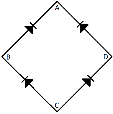
Figure shows a full wave bridge rectifier circuit. The input a.c. is connected across

(A) A and B
(B) A and C
(C) B and D
(D) B and C

Answer
577.5k+ views
Hint:
In this circuit of the full wave rectifier, if the connection is made across the points A and C then the points B and D will have the same voltage. So the output will become zero. Hence the connection should be made across BD.
Complete step by step answer:
The bridge rectifier consists of four diodes which are connected in a bridge formation. During one half cycle two of the diodes conduct whereas, during the other half cycle, the other 2 diodes conduct in order to give the output after full rectification.
If the connection to the input was made across the points A and C then the points B and D will be the output of the rectifier. Then these points B and D will have the same voltage as the point C. Then the output will be zero. So the input can’t be placed at the points A and C.
So the input of the full wave bridge rectifier will have to be put at the points B and D so that the output will be placed at the points A and C and hence the bridge rectifier will work properly.
So the correct answer will be option (D).
Note:
The full wave rectifiers make use of both the half cycles of the input wave alternating current and then give the output as dc. The full wave rectifier is more efficient than the half wave rectifier as it uses both the half cycle of the alternating current input. The bridge rectifiers due to their low cost are used widely in power supply circuits. They are also used to detect the amplitude of the modulated radio signals.
Recently Updated Pages
Master Class 12 Economics: Engaging Questions & Answers for Success

Master Class 12 Physics: Engaging Questions & Answers for Success

Master Class 12 English: Engaging Questions & Answers for Success

Master Class 12 Social Science: Engaging Questions & Answers for Success

Master Class 12 Maths: Engaging Questions & Answers for Success

Master Class 12 Business Studies: Engaging Questions & Answers for Success

Trending doubts
Why cannot DNA pass through cell membranes class 12 biology CBSE

Differentiate between insitu conservation and exsitu class 12 biology CBSE

Draw a neat and well labeled diagram of TS of ovary class 12 biology CBSE

In a human foetus the limbs and digits develop after class 12 biology CBSE

AABbCc genotype forms how many types of gametes a 4 class 12 biology CBSE

The correct structure of ethylenediaminetetraacetic class 12 chemistry CBSE


