


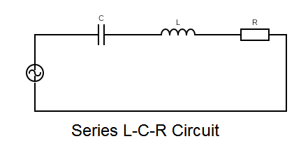
A series LCR circuit is connected to an ac source. Using the phasor diagram, derive the expression for the impedance of the circuit. Plot a graph to show the variation of current with frequency of the source, explaining the nature of its variation.
Answer
567.3k+ views
Hint: Draw the phasor diagram from the sense of the voltages across the each component in the circuit and use Pythagoras theorem to find the impedance of the circuit.
Complete answer:
We know that the voltage drop across a resistance is $ {V_R} = IR $ where, $ I $ is the current in the circuit and $ R $ is the resistance of the circuit. The voltage across a inductor coil is, $ {V_L} = I{X_L} $ where $ {X_L} = j\omega L $ is the inductive impedance, $ L $ is the inductance of the coil, $ \omega $ is the frequency of the AC source.
The voltage drop across a capacitor is $ {V_C} = I{X_C} $ where , $ {X_C} = \dfrac{1}{{j\omega C}} $ is the capacitive impedance, $ C $ is the capacitance of the capacitor.
Now, for a series LCR circuit, we can observe the voltage drops across each component as by the equations given above.
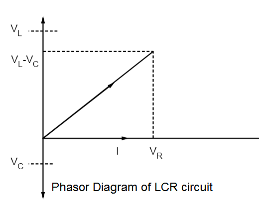
Now, we have to plot the phasor diagram. We can see that the voltage across $ L $ is a pure imaginary type quantity so it will be leading current $ I $ by $ {90^ \circ } $ (is on the positive $ Y $ axis). The voltage across $ C $ is also a pure imaginary type quantity, hence it will lag current by $ {90^ \circ } $ ( since $ \dfrac{1}{j} = - j $ ), so it will be on the negative $ Y $ axis of the phasor diagram, . Voltage across $ R $ is a real quantity hence it will be in phase with the current $ I $ . The net voltage drop across the circuit will be a complex quantity as $ {V_{NET}} = {V_R} + {V_C} + {V_L} $
So,
$
= IR + I{X_C} + I{X_L} \\
= IR + jI\left( {\omega L - \dfrac{1}{{\omega C}}} \right) \\
$
So, the $ {V_{NET}} $ will be on the positive complex $ XY $ plane. So, the phasor diagram of the circuit is given in the diagram.
Now, we want to find the impedance $ Z $ of the circuit.
If we use Pythagoras theorem from the diagram (or take modulus on the both sides of the expression of $ {V_{NET}} $ ) we get,
$ {V_{NET}}^2 = {V_R}^2 + {({V_L} - {V_C})^2} $
Now, putting the values of $ {V_L} $ , $ {V_C} $ and $ {V_R} $ in the phase or complex plane.
$ \therefore {(IZ)^2} = {(IR)^2} + {(I\omega L - \dfrac{I}{{\omega C}})^2} $
Cancelling out $ I $ from both sides we get,
$ \Rightarrow {(Z)^2} = {(R)^2} + {(\omega L - \dfrac{1}{{\omega C}})^2} $
Hence taking square root of the equation we get the expression of impedance as,
$ \Rightarrow Z = \sqrt {{{(R)}^2} + {{(\omega L - \dfrac{1}{{\omega C}})}^2}} $
This is our required expression for impedance of the circuit.
Now, to observe the nature of the variation of current vs. frequency, we have to observe this expression of the impedance,
We can write, $ {V_{NET}} $ as, $ {V_{NET}} = I\sqrt {{{(R)}^2} + {{(\omega L - \dfrac{1}{{\omega C}})}^2}} $
Hence, current is given as, $ I = \dfrac{{{V_{NET}}}}{{\sqrt {{{(R)}^2} + {{(\omega L - \dfrac{1}{{\omega C}})}^2}} }} $
We can see the variation of current with frequency is shown in the graph, when $ {V_{NET}} $ , $ R,L $ and $ C $ are constants.
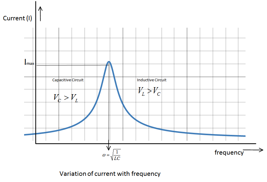
So, you can see, current will be maximum when the quantity $ \sqrt {{{(R)}^2} + {{(\omega L - \dfrac{1}{{\omega C}})}^2}} $ will be minimum.
This quantity will be minimum when , $ \omega L = \dfrac{1}{{\omega C}} $ , this is called the resonance condition. At resonance $ {I_{Max}} = \dfrac{{{V_{NET}}}}{R} $ and resonance frequency is $ \omega = \sqrt {\dfrac{1}{{LC}}} $ .
For frequencies greater than resonant frequency, $ \omega > \sqrt {\dfrac{1}{{LC}}} $ ,
$
\omega L > \dfrac{1}{{\omega C}} \\
\therefore {V_L} > {V_C} \\
$
Hence, the circuit is inductive.
For, frequencies lesser than resonant frequency , $ \omega < \sqrt {\dfrac{1}{{LC}}} $
$
\omega L < \dfrac{1}{{\omega C}} \\
\therefore {V_C} > {V_L} \\
$
Hence, the circuit will be capacitive in this condition.
Note:
For a circuit with reactive elements, phase difference between current and voltage across the capacitor is always $ - {90^ \circ } $ or the voltage lags the current. Whereas, for an inductor phase difference between current and voltage across the inductor is always $ {90^ \circ } $ or the voltage leads the current.
Complete answer:
We know that the voltage drop across a resistance is $ {V_R} = IR $ where, $ I $ is the current in the circuit and $ R $ is the resistance of the circuit. The voltage across a inductor coil is, $ {V_L} = I{X_L} $ where $ {X_L} = j\omega L $ is the inductive impedance, $ L $ is the inductance of the coil, $ \omega $ is the frequency of the AC source.
The voltage drop across a capacitor is $ {V_C} = I{X_C} $ where , $ {X_C} = \dfrac{1}{{j\omega C}} $ is the capacitive impedance, $ C $ is the capacitance of the capacitor.
Now, for a series LCR circuit, we can observe the voltage drops across each component as by the equations given above.
Now, we have to plot the phasor diagram. We can see that the voltage across $ L $ is a pure imaginary type quantity so it will be leading current $ I $ by $ {90^ \circ } $ (is on the positive $ Y $ axis). The voltage across $ C $ is also a pure imaginary type quantity, hence it will lag current by $ {90^ \circ } $ ( since $ \dfrac{1}{j} = - j $ ), so it will be on the negative $ Y $ axis of the phasor diagram, . Voltage across $ R $ is a real quantity hence it will be in phase with the current $ I $ . The net voltage drop across the circuit will be a complex quantity as $ {V_{NET}} = {V_R} + {V_C} + {V_L} $
So,
$
= IR + I{X_C} + I{X_L} \\
= IR + jI\left( {\omega L - \dfrac{1}{{\omega C}}} \right) \\
$
So, the $ {V_{NET}} $ will be on the positive complex $ XY $ plane. So, the phasor diagram of the circuit is given in the diagram.
Now, we want to find the impedance $ Z $ of the circuit.
If we use Pythagoras theorem from the diagram (or take modulus on the both sides of the expression of $ {V_{NET}} $ ) we get,
$ {V_{NET}}^2 = {V_R}^2 + {({V_L} - {V_C})^2} $
Now, putting the values of $ {V_L} $ , $ {V_C} $ and $ {V_R} $ in the phase or complex plane.
$ \therefore {(IZ)^2} = {(IR)^2} + {(I\omega L - \dfrac{I}{{\omega C}})^2} $
Cancelling out $ I $ from both sides we get,
$ \Rightarrow {(Z)^2} = {(R)^2} + {(\omega L - \dfrac{1}{{\omega C}})^2} $
Hence taking square root of the equation we get the expression of impedance as,
$ \Rightarrow Z = \sqrt {{{(R)}^2} + {{(\omega L - \dfrac{1}{{\omega C}})}^2}} $
This is our required expression for impedance of the circuit.
Now, to observe the nature of the variation of current vs. frequency, we have to observe this expression of the impedance,
We can write, $ {V_{NET}} $ as, $ {V_{NET}} = I\sqrt {{{(R)}^2} + {{(\omega L - \dfrac{1}{{\omega C}})}^2}} $
Hence, current is given as, $ I = \dfrac{{{V_{NET}}}}{{\sqrt {{{(R)}^2} + {{(\omega L - \dfrac{1}{{\omega C}})}^2}} }} $
We can see the variation of current with frequency is shown in the graph, when $ {V_{NET}} $ , $ R,L $ and $ C $ are constants.
So, you can see, current will be maximum when the quantity $ \sqrt {{{(R)}^2} + {{(\omega L - \dfrac{1}{{\omega C}})}^2}} $ will be minimum.
This quantity will be minimum when , $ \omega L = \dfrac{1}{{\omega C}} $ , this is called the resonance condition. At resonance $ {I_{Max}} = \dfrac{{{V_{NET}}}}{R} $ and resonance frequency is $ \omega = \sqrt {\dfrac{1}{{LC}}} $ .
For frequencies greater than resonant frequency, $ \omega > \sqrt {\dfrac{1}{{LC}}} $ ,
$
\omega L > \dfrac{1}{{\omega C}} \\
\therefore {V_L} > {V_C} \\
$
Hence, the circuit is inductive.
For, frequencies lesser than resonant frequency , $ \omega < \sqrt {\dfrac{1}{{LC}}} $
$
\omega L < \dfrac{1}{{\omega C}} \\
\therefore {V_C} > {V_L} \\
$
Hence, the circuit will be capacitive in this condition.
Note:
For a circuit with reactive elements, phase difference between current and voltage across the capacitor is always $ - {90^ \circ } $ or the voltage lags the current. Whereas, for an inductor phase difference between current and voltage across the inductor is always $ {90^ \circ } $ or the voltage leads the current.
Recently Updated Pages
Master Class 12 Economics: Engaging Questions & Answers for Success
Master Class 12 English: Engaging Questions & Answers for Success
Master Class 12 Social Science: Engaging Questions & Answers for Success
Master Class 12 Maths: Engaging Questions & Answers for Success
Master Class 12 Physics: Engaging Questions & Answers for Success
Master Class 9 General Knowledge: Engaging Questions & Answers for Success
Trending doubts
Which are the Top 10 Largest Countries of the World?
Draw a labelled sketch of the human eye class 12 physics CBSE
Differentiate between homogeneous and heterogeneous class 12 chemistry CBSE
Why is the cell called the structural and functional class 12 biology CBSE
Draw ray diagrams each showing i myopic eye and ii class 12 physics CBSE
Which is the correct genotypic ratio of mendel dihybrid class 12 biology CBSE