


What is Ripple Factor?
Even after the process of rectification, there would always be a fluctuating component that can be observed in the output of the rectifier, which causes serious issues in the output obtained. With these small fluctuations, we find the output affects the sensitive devices and their working. The ripple factor is one among the vital characteristics necessary when designing a power converter. The ripple factor measures what quantity deviation the converter output parameter has, like the output current, from its nominal designed value. Let’s read ahead to know how we can define ripple factor and learn more details about it.
Ripple Factor Formula
Ripple is the fluctuating AC component present in the output after rectification. The output of a rectifier can be either DC voltage or current. Therefore, AC fluctuating components present in DC output voltage are called voltage ripple and the ripple in DC current output is called current ripple. Ripple often comes because of the presence of circuit elements like diodes or thyristors.
The ripple factor is the ratio of the RMS value of the AC component that is present in the rectifier output to the average value of the rectifier output. The formula for the ripple factor is as follows.
$ Ripple factor = \frac{RMS value of\hspace{1mm} AC \hspace{1mm} component\hspace{1mm} in \hspace{1mm} the\hspace{1mm} rectifier\hspace{1mm} output}{Average \hspace{1mm} value\hspace{1mm} of\hspace{1mm} rectifier\hspace{1mm} output}$
Depending on the ripple current or voltage, we measure the formula will vary for the ripple factor.
For ripple voltage, the formula is as follows:
$\Gamma=\sqrt {\left( \dfrac {V_{rms}}{V_{dc}}\right)^2 -1}$
For ripple current,
$\Gamma=\sqrt {\left( \dfrac {I_{rms}}{I_{dc}}\right)^2 -1}$
Generally, the ripple factor is denoted in percentage, the lesser the ripple factor higher the efficiency of the output.
The ripple factor value in a half wave rectifier is 1.21 while for a full wave rectifier it is 0.482. Measurement of ripple basically denotes the purity of the rectified output. The more the ripple factor, the lesser will be the purity of rectified DC output, which means more will be the presence of fluctuating AC components. Therefore we take certain measures to reduce the ripple factor.
The ripple factor is generally denoted in percentage as mentioned before. The percentage of ripple factor is obtained by just multiplying the ratio by 100. Let’s say 2.2 % of ripple content in output current, that means 2.2 A RMS alternating component of current is present against the actual 100 A DC current output. Similarly, 2.2 % ripple content in output voltage means that 2.2 V RMS alternating component of voltage is present against the actual 100 V DC voltage output.
Significance of Ripple Factor
The single-phase rectifier’s output isn't entirely DC. It additionally has some AC components. Ripple value describes the AC elements.
The magnitude of the AC component within the output is indicated by the ripple issue.
A higher value of the ripple factor indicates that the rectifier’s output features a larger AC component.
Ripple Factor of Bridge Rectifier
A full wave rectifier that converts sinusoidal AC input to DC is called a bridge rectifier. This circuit includes four diodes, these are connected in such a way that 2 of them conduct throughout the positive half cycle of the supply input and therefore the other 2 diodes conduct throughout the negative half cycle of the rectifier.
For a bridge rectifier, the ripple factor is 0.482. In reality, the value of the ripple factor is simply determined by the wave form of the output current or load voltage.
Ripple Factor of a Full Wave Rectifier
Consider a full wave rectifier, where the output of the single phase full rectifier is as shown below.
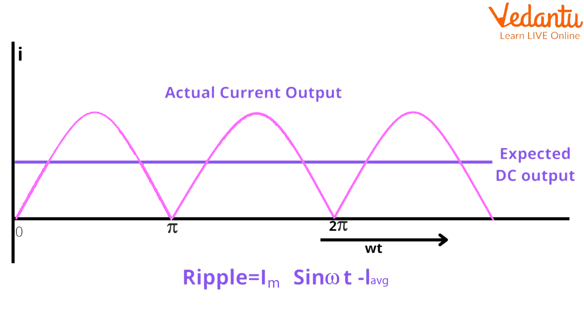
Input and Output of Full Wave Rectifier
If we observe the output of the full wave rectifier, it is not rectified. We were expecting pure DC but the actual output is disturbed. Let’s find the ripple factor of a full-wave rectifier.
For a full wave rectifier
$I_{rms}=\frac{I_{m}}{\sqrt{2}}$
Where Im is the maximum current.
$I_{dc}=\frac{2I_{m}}{\pi}$
$Ripple factor = \sqrt{(\frac{\frac{I_{m}}{\sqrt{2}}}{\frac{2I_{m}}{\pi}})^{2}}-1 = 0.48$
That is, the full wave factor dc component is more than AC.
Ripple Frequency
It is the frequency of the residual AC voltage after it has been rectified to DC in a power supply. Ripple frequency depends upon the rectifier we use. For a half wave rectifier, its input frequency or supplied frequency is 50Hz, and the ripple frequency for the halfwave rectifier is the same as that of the supplied frequency, which is 50Hz. In general ripple, the frequency is double the input frequency. For a full-wave rectifier, its input frequency is 60Hz and therefore its ripple frequency is 120Hz.
Effects of Ripples
Some equipment can work with the ripples, while some of the sensitive test instruments and audio devices do not work properly with working supplies having high ripple. The effects of ripple are as follows:
It causes heating and damage to the capacitors
Negatively affects sensitive instrumentation
Interferes with TV displays
Causes noise to audio circuits
Causes errors in digital circuits, data corruption, and incorrect outputs in logic circuits
How to Overcome Ripple?
We can overcome the ripple which comes in the rectified output by introducing filters. One way is by introducing capacitors, which are smoothing capacitors that convert the ripple voltage into a smoother dc voltage. Aluminum electrolytic capacitors are widely used for this purpose and with capacitances of 100uF or more. The dc pulses charge the capacitor to the peak voltage. The Factors to be considered when selecting the capacitor are the voltage and the value of capacitance. A lower value of capacitance will not be effective and capacitors may be connected in parallel to increase the value. Most of the good power supplies have ripples better than 10mV RMS.
Summary
When the AC waveform is rectified with a rectifier unit, the rectified output isn't perfectly DC rather the DC output has pulsating components referred to as AC components. The ripple factor is a vital parameter for assessing the effectiveness of the rectifier. The lower ripple factor value shows that the ripples in the DC output are less and also the efficiency of the rectifier is better. Moreover, the higher value shows that more fluctuating AC elements are present within the rectified output.
FAQs on Ripple Factor of Full Wave Rectifier
1. What is the ripple factor of a full-wave rectifier and why is it important?
The ripple factor (γ) is a measure that quantifies the amount of residual alternating current (AC) component, or 'ripple', present in the rectified direct current (DC) output of a rectifier. In essence, it tells you how 'pure' the DC signal is. It is important because a lower ripple factor signifies a smoother, more stable DC output, which is crucial for the proper functioning of most electronic circuits. For a full-wave rectifier, the ripple factor is significantly lower than that of a half-wave rectifier, making it more effective.
2. What is the formula to calculate the ripple factor for a full-wave rectifier, and what is its theoretical value?
The formula for the ripple factor (γ) is derived from the ratio of the RMS value of the AC component of the output voltage to the DC value of the output voltage. The standard formula is:
γ = √( (V_rms / V_dc)² - 1 )
For a full-wave rectifier, the theoretical calculation yields a ripple factor value of 0.482. This means the AC ripple component is about 48.2% of the DC component, indicating a significantly smoother output compared to a half-wave rectifier.
3. Why does the output of a full-wave rectifier contain ripples instead of being pure DC?
A full-wave rectifier converts both polarities of the AC input into a single polarity DC output. However, it does not produce a constant, flat DC voltage. The output is a series of positive pulses that rise from zero to a maximum and then fall back to zero. This pulsating nature means the output voltage is not constant but varies periodically. This variation is the AC component superimposed on the DC voltage, which we refer to as ripples. To get a smoother DC, a filter circuit is required to smoothen these pulses.
4. How does the ripple factor of a full-wave rectifier compare to that of a half-wave rectifier?
The comparison of ripple factors highlights the superior performance of the full-wave rectifier:
The ripple factor for a full-wave rectifier is approximately 0.482 (or 48.2%).
The ripple factor for a half-wave rectifier is approximately 1.21 (or 121%).
A lower value is better. The fact that the ripple factor of a full-wave rectifier is less than half that of a half-wave rectifier shows that its output is significantly smoother and closer to a pure DC signal, making it much more efficient and suitable for power supply applications.
5. How do filter circuits, such as a capacitor filter, affect the ripple factor of a full-wave rectifier?
Filter circuits are essential for reducing the ripple factor. A common method is using a capacitor filter connected in parallel with the load resistor. The capacitor charges to the peak voltage of the rectified waveform. When the pulsating voltage starts to decrease, the capacitor begins to discharge slowly through the load. This process 'fills in the gaps' between the pulses, resulting in a much smoother output voltage. This significantly reduces the amplitude of the ripples and, therefore, lowers the ripple factor, bringing the output much closer to pure DC.
6. What is the relationship between ripple factor, efficiency, and form factor for a full-wave rectifier?
These three parameters are intrinsically linked and describe the performance of a rectifier:
Form Factor: It is the ratio of the RMS value to the average (DC) value of the output. The ripple factor is mathematically related by the formula γ = √(Form Factor² - 1). A form factor closer to 1 indicates fewer ripples.
Efficiency (η): It is the ratio of output DC power to the input AC power. A lower ripple factor implies that less power is wasted in the form of AC components, leading to a higher DC output power and thus higher efficiency. The maximum theoretical efficiency of a full-wave rectifier is 81.2%, which is directly a result of its lower ripple content compared to a half-wave rectifier.
7. In practical terms, why is a low ripple factor crucial for most electronic devices?
A low ripple factor is crucial because most modern electronic devices, especially those with microprocessors, memory, or sensitive sensors, require a very stable and clean DC power supply to function correctly. High ripples in the power supply can lead to:
Performance Issues: In audio amplifiers, ripples can manifest as an audible 'hum'. In digital circuits, they can cause data errors or system crashes.
Component Damage: Fluctuating voltages can stress electronic components, leading to overheating and a shorter lifespan.
Therefore, achieving a low ripple factor through effective rectification and filtering is a fundamental requirement in designing reliable electronic power supplies.