


What is Mesh Analysis?
The electrical circuits are closed loops or paths that create a web of electrical parts through which electrons can move. Simple circuits can be investigated in circuit analysis utilising fundamental techniques like Ohm's law, KVL, and KCL. However, these techniques, along with series and parallel methods, are unreliable for a complicated circuit made up of numerous regulated sources. Therefore, nodal and mesh (or loop) analysis methods are utilised to determine the variables of a branch in such a circuit. Circuit variables like voltage and currents are easily determined in any branch without any effort utilising these traditional methods. Let's examine mesh analysis in more detail.
Mesh and Nodal Analysis
The process used to calculate the current flowing through a planar circuit is called mesh analysis. A planar circuit is characterised as a circuit drawn on a plane surface without any wires crossing one another. Kirchhoff's voltage law is applied in mesh analysis, which determines the currents in each loop. Kirchhoff's current law is applied in nodal analysis, which determines the voltages at each node in an equation.
Supermesh Analysis
When two meshes share a component as a source of current, super mesh analysis is used to solve large, complex circuits.
Mesh Analysis Steps
The following steps are to be followed:
To recognize the meshes and to categorise the mesh currents as moving either clockwise or counterclockwise in loops.
To measure the amount of mesh current that passes through each component.
Kirchhoff's voltage law and then Ohm's law are used to write the mesh equations for all meshes.
By continuing to Step 3, where the mesh equations are solved, the mesh currents are obtained.
Consequently, using the node voltages, every electrical circuit current through any component and its voltage across any component can be calculated.
Mesh Current Analysis
Mesh Current Analysis is a method for determining the currents flowing around a loop or mesh inside of any circuit's closed path.
Closed Circuit Path
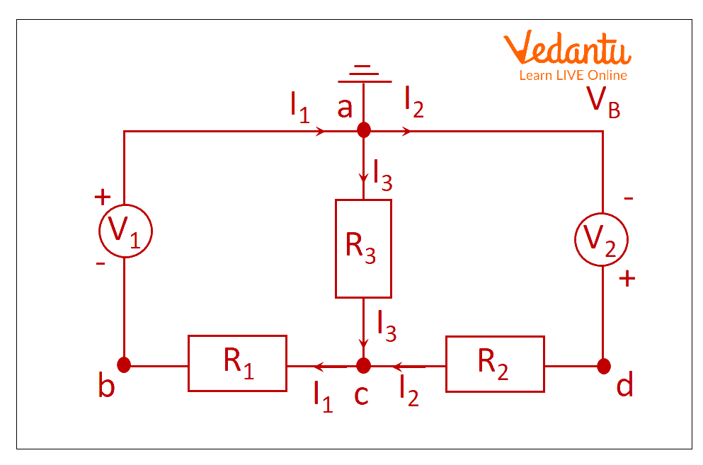
Mesh current analysis from closed circuit path.
Calculating the currents ${I_1}$ and I2 flowing in the two resistors using Kirchhoff's Current Law equations is a straightforward way to reduce the amount of Maths required. As I3 is simply the sum of I1 and I2 (According to Kirchoffs current law), there is no need to compute it.
Here, V1 = 10 V, V2 =20 V, R1 = 10 Ω, R2 = 20 Ω, and R3 = 40 Ω.
We know that V=R x I.
Thus, Kirchhoff's second voltage law is transformed into:
In the first loop, acba R3 is 40 and R1 and R3 are in series that becomes 50 Ohm.
\[10 = 10{I_1} + 40{I_3}\] (Equation No 1)
In the second loop adca, R3 is 40 and R2 and R3 are in series, which becomes 60 Ohm.
\[20 = 40{I_1} + 60{I_2}\] (Equation No 2)
Using this Mesh analysis formula, also known as Loop Analysis or Maxwell's Circulating Currents approach, is a simpler way to solve the circuit shown above. We must designate each "closed loop" acba and adca with a circulating current rather than just labelling the branch currents. Whenever there are Mesh analysis 3 loops, then Kirchhoff's Voltage Law (It says that the sum of voltages must be zero) is applied for every single loop among the three loops with currents I1, I2, and I3.
Interesting Facts of Mesh analysis
Reduces the complexity of the circuit.
Simplifies the calculations and reduces the mathematical equations to solve the circuit.
Identifies the set of meshing equations by using KVL and KCL.
It only applies to flat circuits.
Solved Problems
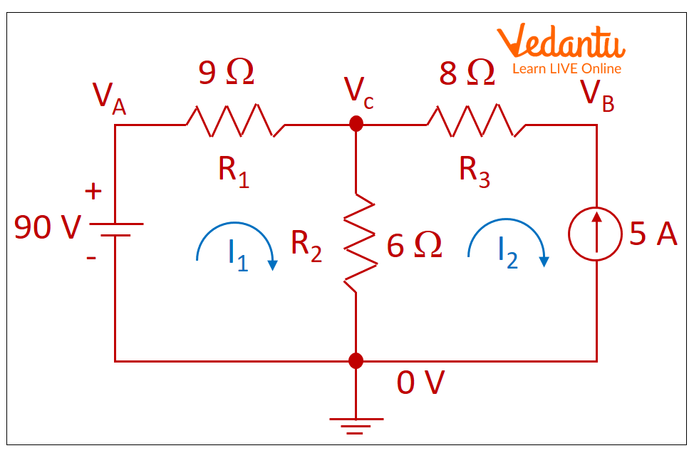
1. The battery value in the Mesh analysis examples circuit is 90 volts, the current source is 5 amps, and the three resistor values are 9 ohms, 6 ohms, and 8 ohms. Calculate the current through each resistor and the potential difference through each resistor using mesh analysis.
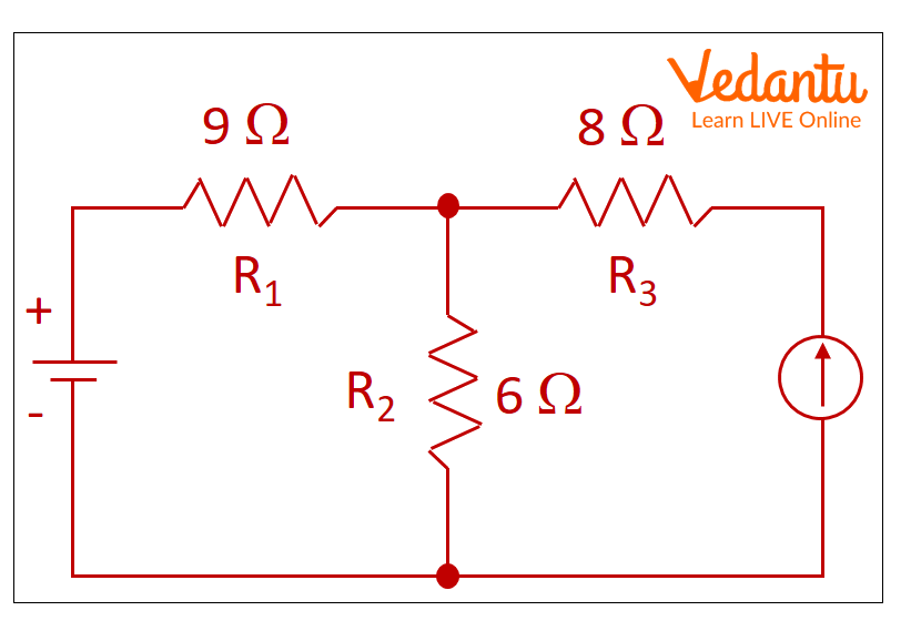
Example circuit
Solution:
At first, let’s define the ground as displayed in the figure.
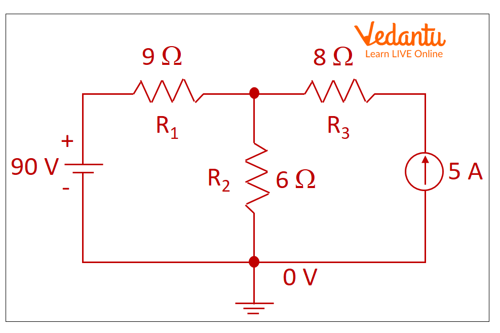
Example Circuit with Ground
Let VA, VB, and VC be the potential, as illustrated in the figure.
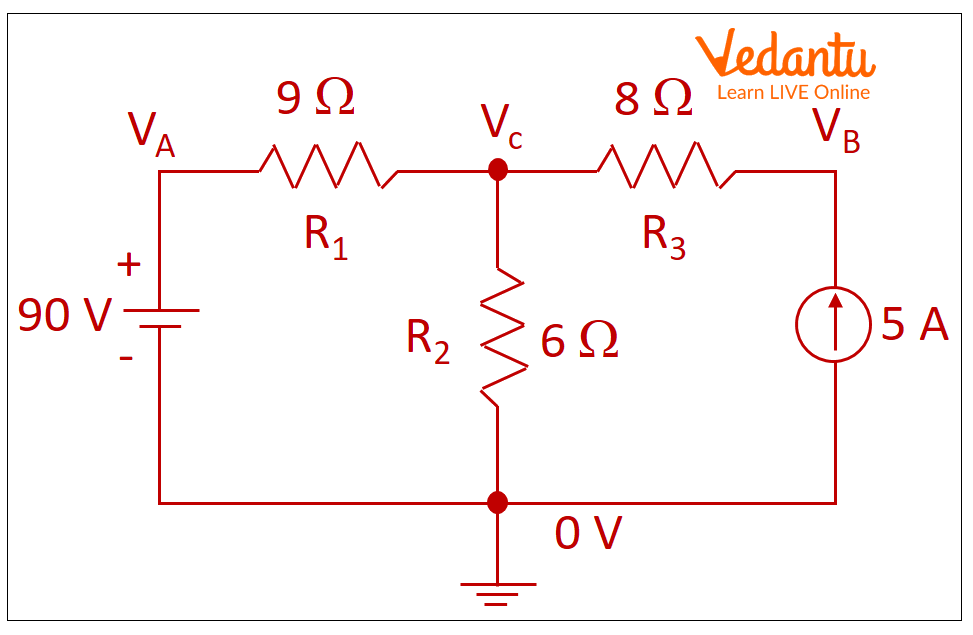
Example Circuit with Ground and Potential
As indicated in the picture, let I1 and I2 represent the currents running through the two loops in a clockwise direction.
Example Circuit with Ground, Potential, and Current Loop
Consider VA, VB, and VC as the potential difference through the resistors R1, R2 and R3, respectively.
Thus,
\[0 = 90 - {I_1}{R_1} - {R_2}({I_1} - {I_2})\]
\[0 = 90 - 9{I_1} - 6({I_1} - {I_2})\]
\[ - 90 = - 15{I_1} + 6{I_2}\]
Dividing the equation with -3, we get
\[ - 30 = - 5{I_1} + 2{I_2}\]
The direction of actual current and I2 are opposite. So, putting I2 as -5, we have
\[{I_1} = 4Amp\]
Thus, 4 Amp current is flowing over R1 and 5 Amp current is flowing over R3.
The potential difference at VA is 90 V.
The potential difference at VB is given by VB = (I1 + I2) R2.
So, VB is 54 V.
The potential difference at VC is given by VC = I2 R3.
So, VC is 40 V.
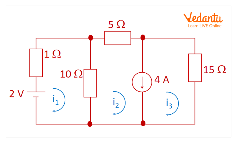
2. Determine the current through a 10 Ohm resistor using the supermesh analysis in the given circuit.
Example Circuit with Current Loops
Calculate the current through a 10 Ohm resistor using supermesh analysis.
Solution:
By application of KVL to mesh 1, we have
\[1{i_1} + 10({i_1} - {i_2}) = 2\]
\[11{i_1} - 10{i_2} = 2..........{\rm{(1)}}\]
Here, mesh 2 and 3 have 4A current source and as a result form a supermesh. The current from current source 4A is aligned with i3, so supermesh current is,
\[i = {i_2} - {i_3}\]
\[{i_2} - {i_3} = 4..........{\rm{(2)}}\]
By application of KVL to supermesh outer loop, we have
\[ - 10({i_2} - {i_1}) - 5{i_2} - 15{i_3} = 0\]
\[10{i_1} - 15{i_2} - 15{i_3} = 0..........(3)\]
Solution of equations 1, 2, and 3 give,
\[{i_1} = - 2.35{\rm{ A}}\]
\[{i_2} = - 2.78{\rm{ A}}\]
\[{i_3} = 1.22{\rm{ A}}\]
So, the current through 10 Ohm resistor given by,
\[{i_1} - {i_2} = - 2.35 + 2.78\]
\[{i_1} - {i_2} = 0.43{\rm{ A}}\]
Summary
Nodal and mesh (or loop) analysis methods can be utilised to determine the variables of a branch in such a circuit. Circuit variables like voltage and currents can be easily determined in any branch without any efforts and using these mesh and nodal analysis methods. When two meshes share a component as a source of current, super mesh analysis is used to solve large, complex circuits.
FAQs on Mesh Analysis
1. What is mesh analysis and how is it applied to electrical circuits as per CBSE 2025–26 syllabus?
Mesh analysis is a circuit analysis method used to determine the current in each loop of a planar electrical circuit. The technique involves assigning mesh currents to the smallest closed loops and using Kirchhoff's Voltage Law (KVL) to set up equations. These equations can then be solved to find unknown currents efficiently in accordance with the CBSE 2025–26 requirements.
2. What are the main steps involved in performing mesh analysis in CBSE Class 12 Physics?
The steps for mesh analysis include:
- Identify all the meshes in the circuit.
- Assign a mesh current to each loop (usually clockwise or counterclockwise).
- Apply Kirchhoff’s Voltage Law (KVL) to each mesh to form equations.
- Solve the simultaneous equations to determine the values of mesh currents.
3. How does mesh analysis differ from nodal analysis in exam-based questions?
Mesh analysis focuses on using KVL to calculate loop (mesh) currents, while nodal analysis applies Kirchhoff’s Current Law (KCL) to determine the potential difference (voltage) at circuit nodes. In exam scenarios, mesh analysis is preferred for circuits with fewer loops, whereas nodal analysis is used when there are fewer nodes/quicker to solve for voltages.
4. Why is mesh analysis limited to planar circuits?
Mesh analysis only applies to planar circuits because it requires that no circuit elements cross over one another. Non-planar (complex) circuits cannot have their loops identified unambiguously, making mesh current assignment and equation setup impossible as per standard methodology.
5. What is a supermesh, and how is it used in solving complex circuits?
A supermesh is formed in mesh analysis when two adjacent meshes share a current source. Instead of writing separate equations for each mesh, you combine them into a single 'supermesh' loop, excluding the branch with the current source, and apply KVL to the larger loop. Additional constraint equations are used for the current source itself.
6. Which law underpins mesh analysis, and why is it reliable for exam-level solutions?
Kirchhoff’s Voltage Law (KVL) underpins mesh analysis. It states that the algebraic sum of voltages around any closed circuit loop is zero. This ensures the method is mathematically sound and reliable for determining loop currents in exam-type circuit questions.
7. What are common mistakes students should avoid while solving mesh analysis questions in board exams?
Students should avoid:
- Misidentifying meshes or incorrectly assigning mesh directions
- Missing negative signs for voltage drops
- Incorrectly adding voltage sources and resistances
- Forgetting to include shared component currents in equations
- Not simplifying equations fully before solving for currents
8. How are mesh currents helpful in determining the actual branch currents in a circuit?
Mesh currents are hypothetical values circulating in each closed loop. By expressing actual branch currents as a combination (sum or difference) of mesh currents passing through shared elements, you can calculate the current through any component in the circuit accordingly.
9. Can mesh analysis be applied when circuits have more than two loops? Provide a method.
Yes, mesh analysis can be applied to circuits with any number of loops. Assign a mesh current to each loop, set up as many KVL equations as there are loops, and solve the resulting system of simultaneous equations to find all mesh currents.
10. Why does mesh analysis reduce the complexity of solving circuit problems for board examinations?
Mesh analysis reduces complexity by lowering the number of equations needed, especially for planar circuits. Instead of dealing with every branch, you focus only on meshes, making circuit problems more manageable for examination time constraints.
11. What conceptual errors do students commonly face with mesh vs. branch current analysis?
Students often confuse mesh currents (hypothetical currents assigned to loops) with branch currents (actual current through components). Mesh currents may flow through multiple branches and their combination determines the branch current values.
12. In what types of board exam problems would mesh analysis not be suitable?
Mesh analysis is not suitable for non-planar circuits (where wires cross in 3D) or circuits with too many loops which create excessive equations. In such cases, nodal analysis or other specialized techniques may be more efficient for board exam solutions.