


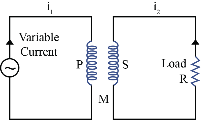
Class 12 Physics Chapter 6 Questions and Answers for Exam Success!


Magnetic Flux: The total number of magnetic lines of force passing normally through an area placed in a magnetic field is equal to the magnetic flux linked with that area.
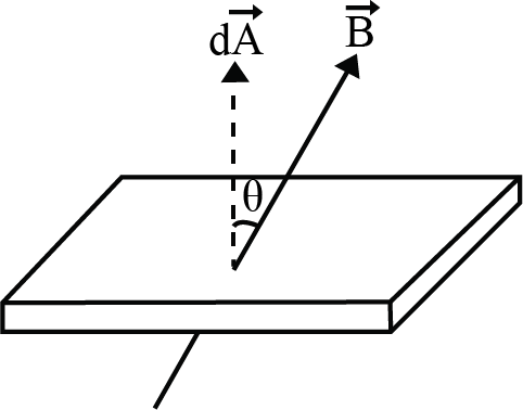
Net flux through the surface
$\phi=\oint \vec{B}.d\vec{A}=BA \cos q$
(θ is the angle between area vector and magnetic field vector) If θ = 0o then φ = BA, If θ = 90o then φ = 0.
Unit and Dimension: Magnetic flux is a scalar quantity. It’s S.I. unit is weber (wb), CGS unit is Maxwell or Gauss × cm2; (1wb = 108 Maxwell).
Faraday’s Laws of EMI
First law: Whenever the number of magnetic lines of force (magnetic flux) passing through a circuit changes an emf is produced in the circuit called induced emf. The induced emf persists only as long as there is change or cutting of flux.
Second law: The induced emf is given by rate of change of magnetic flux linked with the circuit i.e. $e=-\frac{df}{dt}.$ For N turns $e=-N\frac{df}{dt}.$ ; Negative sign indicates that induced emf (e) opposes the change of flux.
Lenz’s law states that the polarity of the induced emf is such that it tends to produce a current which opposes the change in magnetic flux that produces it. The negative sign in the expression for Faraday’s law indicates this fact.
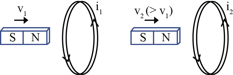
If a bar magnet moves towards a fixed conducting coil, then due to the flux changes an emf, current and charge induces in the coil. If the speed of magnet increases, then induced emf and induced current increases but induced charge remains the same.
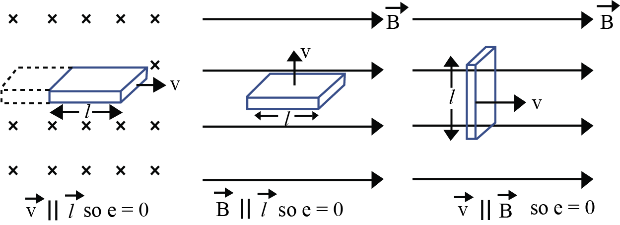
When a metal rod of length l is placed normal to a uniform magnetic field B and moved with a velocity v perpendicular to the field, the induced emf (called motional emf) across its ends is ε = Blv
In motional emf $ \vec{B},\vec{v}$ and $\vec{l}$ are three vectors. If any two vectors are parallel induced emf will be zero.
Changing magnetic fields can set up current loops in nearby metal (any conductor) bodies. They dissipate electrical energy as heat. Such currents are eddy currents.
Inductance is the ratio of the flux-linkage to current. It is equal to $N\frac{\phi}{I}$.
The circuit behavior of an inductor is quite different from that of a resistor. while a resistor opposes the current i, an inductor opposes the change $\frac{di}{dt}$ in the circuit.
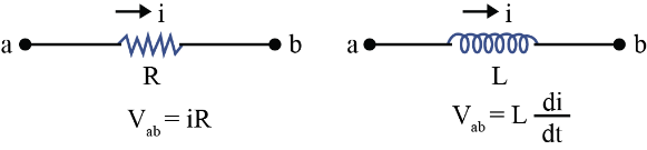
If main current through a coil increases (i↑) so $\frac{di}{dt}$ will be positive (+ve), hence induced emf e will be negative (i.e. opposite emf) ⇒ Enet = E – e

A changing current in a coil 1 (coil P) can induce an emf in a nearby coil 2 (coil S).
This relation is given by,
$\varepsilon _1=-M_{12}\frac{dI_2}{dt}
The quantity M12 is called mutual inductance of coil 1 with respect to coil 2. One can similarly define M21. There exists a general equality,
M12 = M21
When a current in a coil changes, it induces a back emf in the same coil. The self-induced emf is given by,
$\varepsilon =-L\frac{dI}{dt}$
L is the self-inductance of the coil. It is a measure of the inertia of the coil against the change of current through it.
The self-inductance of a long solenoid, the core of which consists of a magnetic material of relative permeability μr, is given by L = μr μ0 n2 Al
where A is the area of cross-section of the solenoid, l its length and n the number of turns per unit length.
In an ac generator, mechanical energy is converted to electrical energy by virtue of electromagnetic induction. If coil of N turn and area A is rotated at ν revolutions per second in a uniform magnetic field B, then the motional emf produced is
ε = NBA (2πf) sin (2πft)
where we have assumed that at time t = 0 s, the coil is perpendicular to the field.
Access NCERT Solutions for Class 12 Physics Chapter 6 – Electromagnetic Induction
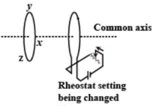
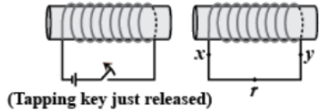
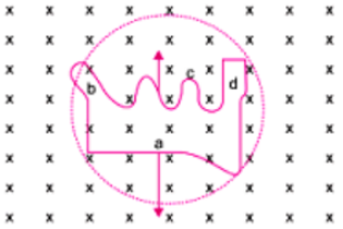
1. Predict the direction of induced current in the situations described by the following figures (a) to (f).
a)
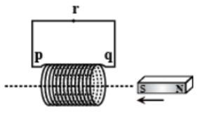
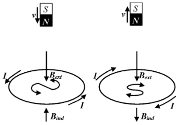
Ans: The direction of the induced current in a closed loop could be given by Lenz’s law. The following pairs of figures show the direction of the induced current when the North pole of a bar magnet is moved towards and away from a closed loop respectively.
Now, by using Lenz’s rule, the direction of the induced current in the given situation is found to be along qrpq.
b)
Ans: On using Lenz’s law, we find the direction of the induced current here to be along prqp.
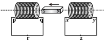
c)
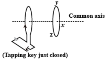
Ans: Using Lenz’s law, we find the direction of the induced current to be along yzxy.
d)
Ans: Using Lenz’s law, we find the direction of the induced current to be along zyxz.
e)
Ans: Using Lenz’s law, we found the direction of the induced current to be along xryx.
f)
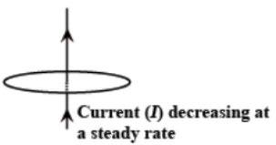
Ans: Here we find that, no current is induced since the field lines are lying in the same plane as that of the closed loop.
2. Use Lenz’s law to determine the direction of induced current in the situations described by Figure:
a) A wire of irregular shape turning into a circular shape;
Ans: According to Lenz's law, the direction of the induced emf is such that it tends to produce a current that would oppose the change in the magnetic flux that produced it.
The wire is expanding to form a circle, which means that force would be acting outwards on each part of the wire because of the magnetic field (acting in the downwards direction). Now, the direction of induced current should be such that it will produce magnetic field in the upward direction (towards the reader). Therefore, the force on wire will be towards the inward direction, i.e., induced current would be flowing in anticlockwise direction in the loop from cbad.
b) A circular loop being deformed into a narrow straight wire.
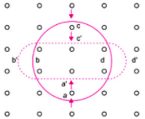
Ans: On deforming the shape of a circular loop into a narrow straight wire, the flux piercing the surface decreases. Therefore, the induced current flows along abcd according to Lenz’s law.
3. A long solenoid with 15 turns per cm has a small loop of area $2.0c{{m}^{2}}$placed inside the solenoid normal to its axis. If the current carried by the solenoid changes steadily from \[2.0A\] to \[4.0A\]in\[0.1s\], what is the induced emf in the loop while the current is changing?
Ans: We are given the following information:
Number of turns on the solenoid \[=15turns/cm=1500turns/m\]
Number of turns per unit length, \[n=1500\text{ }turns\]
The solenoid has a small loop of area,$A=2.0c{{m}^{2}}=2\times {{10}^{-4}}{{m}^{2}}$
Current carried by the solenoid changes from\[2A\text{ }to\text{ }4A\].
Now, the change in current in the solenoid, \[di=4-2=2A\]
Change in time, \[dt=0.1\text{ }s\]
Induced emf in the solenoid could be given by Faraday’s law as:
$\varepsilon =\frac{d\phi }{dt}$………………………… (1)
Where, induced flux through the small loop, $\phi =BA$…………… (2)
Equation (1) would now reduce to:
$\varepsilon =\frac{d}{dt}\left( BA \right)=A{{\mu }_{0}}n\times \left( \frac{di}{dt} \right)$
Substituting the given values into this equation, we get,
$\varepsilon =2\times {{10}^{-4}}\times 4\pi \times {{10}^{-7}}\times 1500\times \frac{2}{0.1}$
$\therefore \varepsilon =7.54\times {{10}^{-6}}V$
Therefore, the induced voltage in the loop is found to be, $\varepsilon =7.54\times {{10}^{-6}}V$.
4. A rectangular wire loop of sides 8cm and 2cm with a small cut is moving out of a region of uniform magnetic field of magnitude 0.3T directed normal to the loop. What is the emf developed across the cut if the velocity of the loop is in a direction normal to the:
a) longer side? For how long does the induced voltage last in this case?
Ans: We are given the following,
Length of the rectangular wire, \[l=8cm=0.08\text{ }m\]
Width of the rectangular wire, \[b=2cm=0.02m\]
Now, the area of the rectangular loop,
$A=lb=0.08\times 0.02=16\times {{10}^{-4}}{{m}^{2}}$
Magnetic field strength, \[B=0.3T\]
Velocity of the loop, \[v=1\text{ }cm/s=0.01\text{ }m/s\]
Emf developed in the loop could be given as:
\[\varepsilon =Blv\]
Substituting the given values,
$\varepsilon =0.3\times 0.08\times 0.01=2.4\times {{10}^{-4}}V$
Time taken to travel along the width, $t=\frac{Distance\text{ }travelled}{\text{velocity}}=\frac{b}{v}$
$\Rightarrow t=\frac{0.02}{0.01}=2s$
Therefore, the induced voltage is found to be $2.4\times {{10}^{-4}}V$which lasts for 2s.
b) shorter side of the loop? For how long does the induced voltage last in this case?
Ans: We know that, Emf developed in the loop could be given as:
\[\varepsilon =Blv\]
Substituting the given values,
$\varepsilon =0.3\times 0.02\times 0.01=0.6\times {{10}^{-4}}V$
Time taken to travel along the width, $t=\frac{Distance\text{ }travelled}{\text{velocity}}=\frac{l}{v}$
$\Rightarrow t=\frac{0.08}{0.01}=8s$
Therefore, the induced voltage is found to be $0.6\times {{10}^{-4}}V$which lasts for 8s.
5. A \[1.0m\]long metallic rod is rotated with an angular frequency of $400rad{{s}^{-1}}$about an axis normal to the rod passing through its one end. The other end of the rod is in contact with a circular metallic ring. A constant and uniform magnetic field of \[0.5T\]parallel to the axis exists everywhere. Calculate the emf developed between the centre and the ring.
Ans: We are given the following:
Length of the rod, \[l=1m\]
Angular frequency, $\omega =400rad/s$
Magnetic field strength, \[B=0.5T\]
One end of the rod has zero linear velocity, while the other end has a linear velocity of $l\omega $.
Average linear velocity of the rod, $\nu =\frac{l\omega +0}{2}=\frac{l\omega }{2}$
Emf developed between the centre and the ring,
$\varepsilon =Blv=Bl\left( \frac{l\omega }{2} \right)=\left( \frac{B{{l}^{2}}\omega }{2} \right)$
On substituting the given values,
$\therefore \varepsilon =\frac{0.5\times {{\left( 1 \right)}^{2}}\times 400}{2}=100V$
Therefore, the emf developed between the centre and the ring is \[100V\].
6. A circular coil of radius \[8.0cm\]and 20 turns is rotated about its vertical diameter with an angular speed of $50rad{{s}^{-1}}$in a uniform horizontal magnetic field of magnitude $3.0\times {{10}^{-2}}T$. Obtain the maximum and average emf induced in the coil. If the coil forms a closed loop of resistance\[10\Omega \], calculate the maximum value of current in the coil. Calculate the average power loss due to Joule heating. Where does this power come from?
Ans: We are given:
Max induced emf \[=0.603V\]
Average induced emf \[=0V\]
Max current in the coil \[=0.0603A\]
Average power loss \[=0.018W\text{ }\](Power comes from the external rotor)
Radius of the circular coil, \[r=8cm=0.08m\]
Area of the coil, $A=\pi {{r}^{2}}=\pi \times {{\left( 0.08 \right)}^{2}}{{m}^{2}}$
Number of turns on the coil, \[N=20\]
Angular speed, $\omega =50rad/s$
Magnetic field strength, $B=3\times {{10}^{-2}}T$
Resistance of the loop, \[R=10\text{ }\Omega \]
Maximum induced emf could be given as:
$\varepsilon =N\omega AB=20\times 50\times \pi \times {{\left( 0.08 \right)}^{2}}\times 3\times {{10}^{-2}}$
$\therefore \varepsilon =0.603V$
The maximum emf induced in the coil is found to be \[0.603V\].
Over a full cycle, the average emf induced in the coil is found to be zero.
Maximum current is given as:
$I=\frac{\varepsilon }{R}$
$\Rightarrow I=\frac{0.603}{10}$
$\Rightarrow I=0.0603A$
Average power loss due to joule heating:
$\therefore P=\frac{eI}{2}=\frac{0.603\times 0.0603}{2}=0.018W$
We know that the current induced in the coil would produce a torque opposing the rotation of the coil. Since the rotor is an external agent, it must supply a torque to counter this torque in order to keep the coil rotating uniformly. Hence, dissipated power comes from the external rotor.
7. A horizontal straight wire \[10m\] long extending from east to west is falling with a speed of $5.0m{{s}^{-1}}$, at right angles to the horizontal component of the earth’s magnetic field, $0.30\times {{10}^{-4}}Wb{{m}^{-2}}$.
a) What is the instantaneous value of the emf induced in the wire?
Ans: We are given the following:
Length of the wire, \[l=10m\]
Falling speed of the wire, \[v=5.0m/s\]
Magnetic field strength, $B=0.3\times {{10}^{-4}}Wb{{m}^{-2}}$
Emf induced in the wire is thus found to be,
$\varepsilon =Blv$
\[\Rightarrow \varepsilon =0.3\times {{10}^{-4}}\times 5\times 10\]
$\therefore \varepsilon =1.5\times {{10}^{-3}}V$
Hence, the emf induced in the wire is $\varepsilon =1.5\times {{10}^{-3}}V$.
b) What is the direction of the emf?
Ans: Using Fleming’s rule, we find that the direction of the induced emf is from West to East.
c) Which end of the wire is at the higher electrical potential?
Ans: The eastern end of the wire is the end that is at higher potential.
8. Current in a circuit falls from \[5.0A\text{ }to\text{ }0.0A\]in \[0.1s\]. If an average emf of \[200V\]is induced, give an estimate of the self-inductance of the circuit.
Ans: We are given the following:
Initial current, ${{I}_{1}}=5.0A$
Final current, ${{I}_{2}}=0.0A$
Change in current, $dI={{I}_{1}}-{{I}_{2}}=5A$
Time taken for the change, \[t=0.1s\]
Average emf, $\varepsilon =200V$
For self-inductance (L) of the coil, we have the relation for average emf that could be given as:
$\varepsilon =L\frac{di}{dt}$
$\Rightarrow L=\frac{\varepsilon }{\left( \frac{di}{dt} \right)}$
Substituting the given values we get,
$\therefore L=\frac{200}{\left( \frac{5}{0.1} \right)}=4H$
Therefore, we found the self induction in the coil to be 4H.
9. A pair of adjacent coils has a mutual inductance of \[1.5H\]. If the current in one coil changes from \[0\text{ }to\text{ }20A\text{ }in\text{ }0.5s\], what is the change of flux linkage with the other coil?
Ans: We are given the following,
Mutual inductance of a pair of coils, $\mu =1.5H$
Initial current, ${{I}_{1}}=0A$
Final current, ${{I}_{2}}=20A$
Change in current, $dI={{I}_{2}}-{{I}_{1}}=20-0=20A$
Time taken for the change, \[t=0.5s\]
Induced emf, $\varepsilon =\frac{d\phi }{dt}$…………………. (1)
Where, $d\phi $is the change in the flux linkage with the coil.
Emf is related with mutual inductance could be given as:
$\varepsilon =\mu \frac{dI}{dt}$…………………….. (2)
Equating equations (1) and (2), we get,
$\frac{d\phi }{dt}=\mu \frac{dI}{dt}$
$\Rightarrow d\phi =1.5\times \left( 20 \right)$
$\therefore d\phi =30Wb$
Hence, we found the change in the flux linkage to be 30Wb.
10. A jet plane is travelling towards west at a speed of \[1800km/h\]. What is the voltage difference developed between the ends of the wing having a span of \[25m,\]if the Earth’s magnetic field at the location has a magnitude of $5\times {{10}^{-4}}T$and the dip angle is $30{}^\circ $.
Ans: Speed of the jet plane, \[v=1800\text{ }km/h=500\text{ }m/s\]
Wingspan of jet plane, \[l=25m\]
Earth’s magnetic field strength, $B=5.0\times {{10}^{-4}}T$
Angle of dip, $\delta =30{}^\circ $
Vertical component of Earth’s magnetic field could be given by,
${{B}_{V}}=B\sin \delta $
$\Rightarrow {{B}_{V}}=5\times {{10}^{-4}}\sin 30{}^\circ =2.5\times {{10}^{-4}}T$
Voltage difference between the ends of the wing can be calculated as,
$\varepsilon ={{B}_{V}}\times l\times v$
Substituting the given values,
$\Rightarrow \varepsilon =2.5\times {{10}^{-4}}\times 25\times 500$
$\therefore \varepsilon =3.125V$
Hence, the voltage difference developed between the ends of the wings is \[3.125V\].
11. Suppose the loop in Exercise 6.4 is stationary but the current feeding the electromagnet that produces the magnetic field is gradually reduced so that the field decreases from its initial value of \[0.3T\]at the rate of \[0.02T{{s}^{-1}}\]. If the cut is joined and the loop has a resistance of \[1.6\Omega \]how much power is dissipated by the loop as heat? What is the source of this power?
Ans: We are given,
Sides of the rectangular loop are 8cm and 2cm. Hence, area of the rectangular wire loop would be,
\[A\text{ }=\text{ }length\text{ }\times \text{ }width\]
Initial value of the magnetic field, \[B'=0.3T\]
Rate of decrease of the magnetic field, $\frac{dB}{dt}=0.02T/s$
Emf developed in the loop is given as:
$\varepsilon =\frac{d\phi }{dt}$
Where,
$\varepsilon =\frac{d\left( AB \right)}{dt}=\frac{AdB}{dt}$
$\Rightarrow \varepsilon =16\times {{10}^{-4}}\times 0.02=0.32\times {{10}^{-4}}V$
Resistance of the loop, $R=1.6\Omega $
The current induced in the loop could be given as:
$i=\frac{\varepsilon }{R}$
Substituting the given values,
$\Rightarrow i=\frac{0.32\times {{10}^{-4}}}{1.6}=2\times {{10}^{-5}}A$
Power dissipated in the loop in the form of heat could be given as:
$P={{i}^{2}}R$
$\Rightarrow P={{\left( 2\times {{10}^{-5}} \right)}^{2}}\times 1.6$
$\therefore P=6.4\times {{10}^{-10}}W$
The source of this heat loss is an external agent, which is responsible for changing the magnetic field with time.
12. A square loop of side \[12cm\] with its sides parallel to X and Y axes is moved with a velocity of \[18cm\] in the positive x-direction in an environment containing a magnetic field in the positive z-direction. The field is neither uniform in space nor constant in time. It has a gradient of ${{10}^{-3}}Tc{{m}^{-1}}$ along the negative x-direction (that is it increases by ${{10}^{-3}}Tc{{m}^{-1}}$as one moves in the negative x-direction), and it is decreasing in time at the rate of ${{10}^{-3}}T{{s}^{-1}}$. Determine the direction and magnitude of the induced current in the loop if its resistance is\[4.50m\Omega \].
Ans: We are given,
Side of the square loop, \[s=12cm=0.12m\]
Area of the square loop, $A=0.12\times 0.12=0.0144{{m}^{2}}$
Velocity of the loop, \[v=8cm/s=0.08m/s\]
Gradient of the magnetic field along negative x-direction,
$\frac{dB}{dx}={{10}^{-3}}Tc{{m}^{-1}}={{10}^{-1}}T{{m}^{-1}}$
And, rate of decrease of the magnetic field,
$\frac{dB}{dt}={{10}^{-3}}T{{s}^{-1}}$
Resistance of the loop,
$R=4.5m\Omega =4.5\times {{10}^{-3}}\Omega $
Rate of change of the magnetic flux due to the motion of the loop in a non-uniform magnetic field is given as:
$\frac{d\phi }{dt}=A\times {\frac{dB}{dx}}\times v$
$\Rightarrow \frac{d\phi }{dt}=144\times {{10}^{-4}}{{m}^{2}}\times {{10}^{-1}}\times 0.08$
$\Rightarrow \frac{d\phi }{dt}=11.52\times {{10}^{-5}}T{{m}^{2}}{{s}^{-1}}$
Rate of change of the flux due to explicit time variation in field B is given as:
$\frac{d\phi '}{dt}=A\times \frac{dB}{dx}$
$\Rightarrow \frac{d\phi '}{dt}=144\times {{10}^{-4}}\times {{10}^{-3}}=1.44\times {{10}^{-5}}T{{m}^{2}}{{s}^{-1}}$
Since the rate of change of the flux is the induced emf, the total induced emf in the loop can be calculated as:
\[e=1.44\times {{10}^{-5}}+11.52\times {{10}^{-5}}\]
\[=12.96\times {{10}^{-5}}V\]
\[\therefore \text{Induced current, }i=\frac{e}{R}\]
\[\Rightarrow i=\frac{12.96\times {{10}^{-5}}}{4.5\times {{10}^{-3}}}\]
\[\therefore i=2.88\times {{10}^{-2}}A\]
Therefore, the direction of the induced current is such that there is an increase in the flux through the loop along the positive z-direction.
13. It is desired to measure the magnitude of field between the poles of a powerful loudspeaker magnet. A small flat search coil of area \[2c{{m}^{2}}\]with 25 closely wound turns, is positioned normal to the field direction, and then quickly snatched out of the field region. Equivalently, one can give it a quick \[{{90}^{\circ }}\] turn to bring its plane parallel to the field direction). The total charge flown in the coil (measured by a ballistic galvanometer connected to coil) is\[7.5mC\]. The combined resistance of the coil and the galvanometer is \[0.50\Omega \]. Estimate the field strength of magnet.
Ans: We are given the following:
Area of the small flat search coil, \[A=2c{{m}^{2}}=2\times {{10}^{-4}}{{m}^{2}}\]
Number of turns on the coil, \[N=25\]
Total charge flowing in the coil, \[Q=7.5mC=7.5\times {{10}^{-3}}C\]
Total resistance of the coil and galvanometer, \[R=0.50\Omega \]
Induced current in the coil,
\[I=\frac{\text{Induced emf}(\varepsilon )}{R}\]……………………………………………. (1)
Induced \[emf\] is given as:
\[\varepsilon =-N\frac{d\phi }{dt}\]………………………………………………… (2)
Where, \[d\phi =\text{Induced flux}\]
Combining equations (1) and (2), we get
\[I=-\frac{N\frac{d\phi }{dt}}{R}\]
\[Idt=-\frac{N}{R}d\phi \]……………………………………………. (3)
Initial flux through the coil, \[{{\phi }_{i}}=BA\]
Where,
\[B=\text{Magnetic field strength}\]
Final flux through the coil, \[{{\phi }_{f}}=0\]
Integrating equation (3) on both sides, we have
\[\int{Idt=-\frac{N}{R}\int\limits_{{{\phi }_{i}}}^{{{\phi }_{f}}}{d\phi }}\]
But total charge could be given as, \[Q=\int{Idt}\]
\[\Rightarrow Q=\frac{-N}{R}({{\phi }_{f}}-{{\phi }_{i}})=\frac{-N}{R}(-{{\phi }_{i}})=\frac{+N{{\phi }_{i}}}{R}\]
\[Q=\frac{NBA}{R}\]
\[\Rightarrow B=\frac{QR}{NA}\]
Substituting the given values, we get,
\[\Rightarrow B=\frac{7.5\times {{10}^{-3}}\times 0.5}{25\times 2\times {{10}^{-4}}}\]
\[\therefore B=0.75T\]
Therefore, the field strength of the magnet is found to be \[0.75T\].
14. Figure shows a metal rod PQ resting on the smooth rails AB and positioned between the poles of a permanent magnet. The rails, the rod, and the magnetic field are in three mutual perpendicular directions. A galvanometer G connects the rails through a switch K. Length of the rod\[=15cm\], \[B=0.50T\], resistance of the closed loop containing the rod\[=9.0m\Omega \]. Assume the field to be uniform.
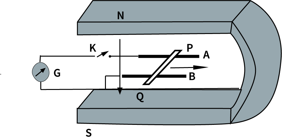
Suppose K is open and the rod is moved with a speed of \[12cm\cdot {{s}^{-1}}\] in the direction shown. Give the polarity and magnitude of the induced \[emf\].
Ans: We are given:
Length of the rod, \[l=15cm=0.15m\]
Magnetic field strength, \[B=0.50T\]
Resistance of the closed loop, \[R=9m\Omega =9\times {{10}^{-3}}\Omega \]
Induced \[emf=9mV\]
Here, polarity of the induced \[emf\] is such that end P shows positive while end Q shows negative ends.
Speed of the rod,\[v=12cm/s=0.12m/s\]
We know that the induced \[emf\] could be given as: \[\varepsilon =Bvl\]
Substituting the given values, we get,
\[\varepsilon =0.5\times 0.12\times 0.15\]
\[\Rightarrow \varepsilon =9\times {{10}^{-3}}v\]
\[\therefore \varepsilon =9mV\]
Therefore, the magnitude of the induced emf is found to be \[\varepsilon =9mV\] an =d the polarity of the induced emf is such that end P shows positive while end Q shows negative.
a) Is there an excess charge built up at the ends of the rods when K is open? What if K is closed?
Ans: Yes; when key K is closed, excess charge could be maintained by the continuous flow of current. When key K is open, there is excess charge built up at both rod ends but when key K is closed, excess charge is maintained by the continuous flow of current.
b) With K open and the rod moving uniformly, there is no net force on the electrons in the rod PQ even though they do experience magnetic force due to the motion of the rod. Explain.
Ans: Magnetic force is cancelled by the electric force that is set-up due to the excess charge of opposite nature at both rod ends. There is no net force on the electrons in rod PQ when key K is open and the rod would move uniformly. This is because magnetic force is cancelled by the electric force set-up due to the excess charge of opposite nature at both ends of the rods.
c) What is the retarding force on the rod when K is closed?
Ans: We know that the retarding force exerted on the rod could be given by, \[F=IBl\]
Where,
\[I=\text{Current flowing through the rod}\]
Substituting the given values, we get,
\[I=\frac{e}{R}=\frac{9\times {{10}^{-3}}}{9\times {{10}^{-3}}}=1A\]
\[\Rightarrow F=1\times 0.5\times 0.15\]
\[\therefore F=75\times {{10}^{-3}}N\]
Therefore, we found the retarding force on the rod when the key K is closed to be,
\[F=75\times {{10}^{-3}}N\]
d) How much power is required (by an external agent) to keep the rod moving at the same speed \[(=12cm\cdot {{s}^{-1}})\] when K is closed? How much power is required when K is open?
Ans: We are given:
Speed of the rod, \[v=12cm/s=0.12m/s\]
Now, power could be given as:
\[P=Fv\]
Substituting the given values, we get,
\[\Rightarrow P=75\times {{10}^{-3}}\times 0.12\]
\[\Rightarrow P=9\times {{10}^{-3}}W\]
\[\therefore P=9mW\]
Therefore, we found the power that is required (by an external agent) to keep the rod moving at the same speed \[(=12cm\cdot {{s}^{-1}})\] when K is closed to be \[P=9mW\]and when key K is open, no power is expended.
e) How much power is dissipated as heat in the closed circuit? What is the source of this power?
Ans: We know that,
\[\text{Power dissipated as heat , P=}{{I}^{2}}R\]
\[\Rightarrow P={{(1)}^{2}}\times 9\times {{10}^{-3}}\]
\[\therefore P=9mW\]
The power dissipated as heat in the closed circuit is found to be \[P=9mW\] and the source of this power is found to be an external agent.
f) What is the induced \[emf\] in the moving rod if the magnetic field is parallel to the rails instead of being perpendicular?
Ans: In this case, no \[emf\]would be induced in the coil because the motion of the rod does not cut across the field lines.
15. An air-cored solenoid with length \[30cm\], area of cross-section \[25c{{m}^{2}}\]and number of turns \[500\], carries a current of \[2.5A\]. The current is suddenly switched off in a brief time of \[{{10}^{-3}}s\]. How much is the average back \[emf\] induced across the ends of the open switch in the circuit? Ignore the variation in magnetic field near the ends of the solenoid.
Ans: We are given the following:
Length of the solenoid, \[l=30cm=0.3m\]
Area of cross-section, \[A=25c{{m}^{2}}=25\times {{10}^{-4}}{{m}^{2}}\]
Number of turns on the solenoid, \[N=500\]
Current in the solenoid, \[I=2.5A\]
Current flows for time, \[t={{10}^{-3}}s\]
Average back \[emf\], \[e=\frac{d\phi }{dt}\]……………………………………. (1)
Where,
\[d\phi =\text{Change in flux=}NAB\]…………………………………………… (2)
Where, \[B=\text{Magnetic field strength}={{\mu }_{0}}\frac{NI}{l}\]………………………… (3)
Where,\[{{\mu }_{0}}=\text{Permeability of free space}=4\pi \times {{10}^{-7}}Tm{{A}^{-1}}\]
Substituting equations (2) and (3) in equation (1), we get,
\[\varepsilon =\frac{{{\mu }_{0}}{{N}^{2}}IA}{lt}\]
\[\Rightarrow \varepsilon =\frac{4\pi \times {{10}^{-7}}\times {{(500)}^{2}}\times 2.5\times 25\times {{10}^{-4}}}{0.3\times {{10}^{-3}}}\]
\[\therefore \varepsilon =6.5V\]
Hence, the average back \[emf\]induced in the solenoid is found to be \[6.5V\].
16.
a) Obtain an expression for the mutual inductance between a long straight wire and a square loop of side a as shown in below figure.
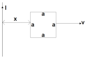
Ans: Consider a small element \[dy\] in the loop at a distance y from the long straight wire (as shown in the given figure).
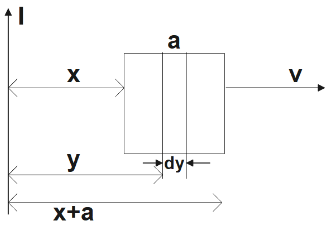
Magnetic flux associated with element \[dy,d\phi =BdA\]
Where, \[dA=\text{Area of element }dy=\text{a }dy\]
\[B=\text{magnetic field at distance y =}\frac{{{\mu }_{0}}I}{2\pi y}\]
\[I=\text{Current in the wire}\]
\[{{\mu }_{0}}=\text{Permeability of free space}=4\pi \times {{10}^{-7}}H/m\]
Carrying out the substitutions accordingly, we get,
\[\Rightarrow d\phi =\frac{{{\mu }_{0}}Ia}{2\pi }\frac{dy}{y}\]
\[\Rightarrow \phi =\frac{{{\mu }_{0}}Ia}{2\pi }\int{\frac{dy}{y}}\]
Now, the limit of y will be from x to \[a+x\], on applying the limits we get,
\[\Rightarrow \phi =\frac{{{\mu }_{0}}Ia}{2x}\int\limits_{x}^{a+x}{\frac{dy}{y}}\]
\[\Rightarrow \phi =\frac{{{\mu }_{0}}Ia}{2\pi }\left[ {{\log }_{e}}y \right]_{x}^{a+x}\]
\[\Rightarrow \phi =\frac{{{\mu }_{0}}Ia}{2\pi }{{\log }_{e}}\left( \frac{a+x}{x} \right)\]
For mutual inductance M, the flux could be given as:
\[\phi =MI\]
\[\Rightarrow MI=\frac{{{\mu }_{0}}Ia}{2\pi }{{\log }_{e}}\left( \frac{a}{x}+1 \right)\]
\[\therefore M=\frac{{{\mu }_{0}}a}{2\pi }{{\log }_{e}}\left( \frac{a}{x}+1 \right)\]
Therefore, the expression for the mutual inductance between the given long straight wire and the square loop of side a is found to be,
\[M=\frac{{{\mu }_{0}}a}{2\pi }{{\log }_{e}}\left( \frac{a}{x}+1 \right)\]
b) Now assume that the straight wire carries a current of \[50A\] and the loop is moved to the right with a constant velocity, \[v=10m/s\]. Calculate the induced \[emf\] in the loop at the instant when\[x=0.2m\]. Take \[a=0.1m\] and assume that the loop has a large resistance.
Ans: We know that, the \[Emf\]induced in the loop, \[\varepsilon =B'av=\left( \frac{{{\mu }_{0}}I}{2\pi x} \right)av\]
We are given the following,
\[I=50A\]
\[x=0.2m\]
\[a=0.1m\]
\[v=10m/s\]
On substituting the given values into the equation, we get,
\[\varepsilon =\frac{4\pi \times {{10}^{-7}}\times 50\times 0.1\times 10}{2\pi \times 0.2}\]
\[\therefore \varepsilon =5\times {{10}^{-5}}V\]
Therefore, induced \[emf\] in the loop at the given instant is found to be, \[\varepsilon =5\times {{10}^{-5}}V\].
17. A line charge \[\lambda \] per unit length is lodged uniformly onto the rim of a wheel of mass M and radius R. The wheel has light non-conducting spokes and is free to rotate without friction about its axis (figure). A uniform magnetic field extends over a circular region within the rim. It is given by,
\[A=-{{B}_{0}}k({r\leq a};a<R)\]
\[A=0\text{ }(\text{otherwise})\]
What is the angular velocity of the wheel after the field is suddenly switched off?
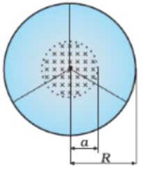
Ans: We know that, the Line charge per unit length \[=\lambda =\frac{\text{Total charge}}{\text{Length}}=\frac{Q}{2\pi r}\]
Where,
r = Distance of the point within the wheel
Mass of the wheel = M
Radius of the wheel = R
Magnetic field, \[\vec{B}=-{{B}_{0}}k\]
At distance r, the magnetic force would be balanced by the centripetal force i.e.,
\[BQv=\frac{M{{v}^{2}}}{r}\]
Where,
\[v=\text{linear velocity of the wheel}\]
\[\Rightarrow \text{B2}\pi \text{r}\lambda =\frac{Mv}{r}\]
\[\Rightarrow v=\frac{B2\pi \lambda {{r}^{2}}}{M}\]
\[\therefore \text{Angular velocity,}\omega =\frac{v}{R}=\frac{B2\pi \lambda {{r}^{2}}}{M}\]
\[{r\leq a}\], and \[{a<R}\] we would get:
\[\omega =\frac{2\pi {{B}_{0}}{{a}^{2}}\lambda }{MR}k\]
Therefore, we found the angular velocity of the wheel after the field is suddenly switched off to be given as,
\[\omega =\frac{2\pi {{B}_{0}}{{a}^{2}}\lambda }{MR}k\]
NCERT Solutions for Class 12 Physics Chapter 6 PDF Download
The NCERT Book Solutions physics class 12 chapter 6 PDF gives solutions on electromagnetic induction perfect for CBSE students. These answers have been explained with diagrams and equations in an easy to understand, step by step manner. Practising from the provided solution will clear the concepts and help students develop logical and reasoning skills.
Moreover, the solution is available in PDF format, which is easily downloadable online. To write a quality answer and score good grades, download electromagnetic induction class 12 solution today.
Electromagnetic Induction Class 12 NCERT Solutions PDF
There are seventeen questions in electromagnetic induction class 12 NCERT PDF, along with detailed solutions. Following the pattern will be helpful for class 12 students appearing for board exams.
Here is a description of the questions and answers provided in electromagnetic induction class 12.
Question 1- Class 12 Physics electromagnetic induction NCERT solutions
Ans: The students need to find the induced current’s direction from the following figure using Lenz’s law.
(Image will be uploaded soon)
Question 2: NCERT solutions class 12 physics electromagnetic induction.
Ans: Students will have to calculate the induced current by utilising Lenz’s law of a figure (a) irregular wire shaped into circle (b) circular loop deformed into a narrow straight wire.
Question 3: Chapter 6 class 12 physics NCERT solutions.
Ans: The third question requires calculating induced EMF in the loop when the number of turns in a solenoid is 15 and the small loop area is 2.0 cm³. The current changes from 2.0A to 4.0A in 0.1s.
Question 4: Class 12 physics ch 6 NCERT solutions.
Ans: Here, the EMF measured across the cut when the velocity of the loop is 1cm s‾², length of rectangular wire is 8 cm, width is 2 cm and the magnetic field strength is 0.3 T. The students have to determine both the shorter and longer side of the loop.
Question 5: Electromagnetic induction class 12 solutions.
Ans: In the fifth question, EMF developed between the centre and ring where the length of the rod is 1m, angular frequency 400 rad/s, magnetic field strength 0.5T parallel to the axis.
Question 6: NCERT solution for class 12 physics chapter 6.
Ans: The question in electromagnetic induction class 12 asks students to calculate the power loss to joule heating where max induce EMF is 0.603v, average induced EMF is 0 v, radius of circular coil is 8.0cm, angular speed is 50 rad s‾¹ and loop resistance is 10Ω.
Question 7 and 8: NCERT solutions for class 12 physics chapter 6 electromagnetic induction
Ans: These questions require students to find the instantaneous value and direction of EMF when the end of the wire is at higher potential and the estimate of self-inductance of the circuit.
Question 9: NCERT physics class 12 chapter 6 solutions.
Ans: Change of flux linkage to other coils where mutual inductance is 1.5H, initial current 0A and final current is 20A.
Question 10: EMI class 12 NCERT solutions.
Ans: Students have to determine the voltage difference between the end of jet plane wings span 25m, speed of jet plane 1800 km/h, earth’s magnetic field 5x10‾⁴ T.
Question 11: Chapter 6 physics class 12 NCERT solutions.
Ans: In question 11, students need to determine the power dissipated by the loop as heat and the source when the initial value of a magnetic field is 0.3T, rate of its decrease is 0.02 Ts‾¹ and loop resistance is 1.6Ω.
Question 12: Electromagnetic induction class 12 NCERT solutions.
Ans: The magnitude and direction of the induced current in the loop, if its resistance is 4.50mΩ, needs to be determined. Here, side of a square circle 12 cm, the velocity is 8cm/s, a gradient of a magnetic field along the x-direction 10‾³ T cm‾¹.
Question 13: Chapter 6 physics class 12 NCERT solutions.
Ans:In the thirteenth question, students need to determine the direction and magnitude of induced current in the loop if its resistance is 4.50Ω. In this side of square circle 12cm, a gradient of magnetic field –x-direction 10‾³T cm‾¹ and decreasing time rate is 10‾³T s‾¹.
Apart from these questions class 12 physics ch 6 NCERT solutions, there are four additional equations with images, which require students to determine field strength of the magnet, polarity and magnitude of induced EMF, a magnetic force with a motion of rod, the power dissipated as a closed circuit, etc.
Marks Distribution of NCERT Solutions Class 12 Physics Electromagnetic Induction
How Electromagnetic Induction Class 12 NCERT Solutions is Beneficial?
The benefits of electromagnetic induction class 12 are as follows:
Experts and scholars prepare these questions and solutions.
The answers are explained with illustrations, figures and formulas.
Step by step explanation of the equations.
It covers the vast sub-topic of the chapter.
By working through the solutions for Physics Chapter 6 in Class 12, students enhance their theoretical understanding and logical reasoning. These 17 questions reinforce the basics of the subject, specifically focusing on the topic of electromagnetic induction in Class 12.
Conclusion
NCERT Solutions for Class 12 Physics Chapter 6 - Electromagnetic Induction are indispensable for students aiming to master the intricate world of electromagnetism. This chapter delves into Faraday's laws of electromagnetic induction, Lenz's law, and the generation of electric currents through changing magnetic fields. These principles underpin the functioning of generators, transformers, and various electrical devices that power our modern world. The availability of comprehensive NCERT solutions in this context is a valuable aid for students, offering clear explanations and solutions to complex problems, enabling a profound understanding of electromagnetic induction. These resources serve as a cornerstone for academic excellence, equipping students with the knowledge and skills necessary for success in physics and its real-world applications.
Other Study Material for CBSE Class 12 Physics Chapter 6
Chapter-Specific NCERT Solutions for Class 12 Physics
Given below are the chapter-wise NCERT Solutions for Class 12 Physics. You can use it as your 12th Physics guide. Go through these chapter-wise solutions to be thoroughly familiar with the concepts.
Related Links for NCERT Class 12 Physics in Hindi
Discover relevant links for NCERT Class 12 Physics in Hindi, offering comprehensive study materials, solutions, and resources to enhance understanding and aid in exam preparation.
Chapter-Specific NCERT Solutions for Class 12 Physics
Given below are the chapter-wise NCERT Solutions for Class 12 Physics. Go through these chapter-wise solutions to be thoroughly familiar with the concepts.

FAQs on NCERT Solutions For Class 12 Physics Chapter 6 Electromagnetic Induction - 2025-26
1. What is the CBSE-prescribed stepwise method to solve numerical questions in NCERT Solutions for Class 12 Physics Chapter 6?
The official CBSE stepwise method for solving numerical questions in Electromagnetic Induction requires you to clearly state the physical law applied (such as Faraday's Law), write all steps sequentially, show substitutions with proper SI units, and present the final answer with reasoning. Each calculation must be explained, ensuring clarity and adherence to the latest CBSE 2025–26 marking scheme.
2. How do NCERT Solutions for Class 12 Physics Chapter 6 ensure accuracy for both intext and exercise questions?
Solutions for every question in this chapter are created by expert faculty following the NCERT answer format designed for CBSE board exams. Each step is checked for correctness, and the reasoning is aligned with the official solution key, so students develop a clear understanding and avoid common conceptual errors.
3. Are solutions for Electromagnetic Induction available in both English and Hindi mediums as per the latest CBSE syllabus?
Yes, NCERT Solutions for Class 12 Physics Chapter 6 are provided in both English and Hindi mediums. The structure and stepwise explanation remain consistent with CBSE norms in both languages to support all students appearing for the 2025–26 board exams.
4. What key laws and concepts are emphasized in NCERT Solutions for Electromagnetic Induction for Class 12?
This chapter’s solutions focus on Faraday’s Laws of Electromagnetic Induction, Lenz’s Law, calculation of induced EMF, and applications like generators, transformers, and induction phenomena. Emphasis is placed on stepwise application of laws, correct use of formulae, and justification of negative signs (opposing flux changes) as required by the CBSE rubric.
5. Can NCERT Solutions alone prepare students for all types of questions in CBSE board exams for Physics Chapter 6?
NCERT Solutions for this chapter comprehensively cover all board-relevant question types: back exercises, intext conceptual queries, derivations, numericals, and application-based problems. When studied thoroughly, these solutions are sufficient for full marks in board contexts, provided the student understands each step and its rationale.
6. Why is following a step-by-step solution important in CBSE Physics exams, especially for topics like Electromagnetic Induction?
CBSE examiners award marks for each correct step, not just the final answer. For Electromagnetic Induction, showing the statement of the law used, deriving or selecting the formula, performing substitutions, and stating the result with units ensures no marks are lost, even if computation errors occur at the end.
7. What are common mistakes students make when using NCERT Solutions for Class 12 Physics Chapter 6, and how can they be avoided?
Frequent errors include incorrect sign conventions in Lenz’s Law, missing SI units, and incomplete reasoning for induced EMF directions. These can be avoided by carefully writing each step, explicitly stating principles used, and always including units and explanations as demonstrated in the structured NCERT Solutions.
8. How do application-based questions in Chapter 6 (like those involving generators or motional EMF) test conceptual clarity?
Such questions require not only formula application but also a conceptual understanding of how changing magnetic fields generate currents, the interplay of motion and field direction, and real-world effects like Joule heating or practical uses in electrical devices. Stepwise explanations in the solutions develop this clarity, linking theory to application.
9. What is the correct procedure to answer derivation-based questions in Electromagnetic Induction as per the CBSE format?
Begin by stating all assumptions and the relevant physical law (e.g., Faraday’s Law), derive the formula step-by-step with intermediate reasoning, justify each mathematical manipulation, and conclude with the final relation and a brief explanation. NCERT Solutions strictly adhere to this structured approach for derivations.
10. How does practicing with official NCERT Solutions help clarify common doubts during Physics board revision?
Consistent practice with NCERT-aligned stepwise solutions helps students understand the required reasoning, mark allocation, and correct use of concepts. It ensures doubts about law application or calculation steps are addressed, providing a reliable revision method before CBSE board exams.
11. What are the best strategies to maximize marks in CBSE Physics Paper using NCERT Solutions for Chapter 6?
- Understand and apply all laws conceptually before attempting numericals.
- Write each step in detail during solutions, using the CBSE pattern.
- Always include SI units and justify negative or positive signs, especially in Lenz’s law applications.
- Relate real-life examples to theory when possible (for long answers).
- Revise key formulas and derivations using the structure given in official NCERT Solutions.
12. What are some misconceptions about induced EMF and current directions, and how do the NCERT Solutions address them?
Students often reverse the direction of induced current or incorrectly apply the right/left hand rules. The NCERT Solutions clarify this by providing diagrams, explicit application of Lenz’s Law, and written justifications for direction, minimizing such conceptual errors in board exams.
13. In what ways are derivations and application-based answers structured differently in NCERT Solutions for Chapter 6?
Derivations require a systematic presentation of each mathematical step, logical reasoning, and physical justification, while application-based answers focus on real-world scenarios, explaining the link between theoretical law and practical outcome. Both types emphasize clarity, formula usage, and reasoning as per CBSE standards.
14. Why is it important to write answers in official CBSE and NCERT format for Physics Chapter 6?
Official CBSE and NCERT format ensures each answer matches marking scheme requirements, demonstrating logical understanding, proper law application, and complete reasoning. This approach increases scoring potential and meets examiner expectations for both short and long answers in Electromagnetic Induction.