


(i) What is an integrated circuit (I.C)? Distinguish between (i) linear I.C and (ii) Digital I.C.
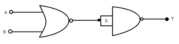
(ii) Identify the equivalent gate for the following circuit and write its truth table.
Answer
576.6k+ views
Hint: Recall the term I.C and its two types. We know that digital appliances have only two output states. In the above figure, output of NAND gate is connected to the input of NOR gate. Draw the truth table for this logic circuit and from the output state, examine which logic gate has the same output state.
Complete step by step answer:
-Integrated Circuit (I.C) is an electronic circuit made up of assembly of electronic components like diodes, transistors, resistors, capacitors, etc,. I.C is generally made up of silicon wafer on which electronic logic gates are burned.
We can now distinguish between linear I.C’s and Digital I.C’s as below.
-Linear I.C’s change the output values for change in input value which takes continuous values from minimum to maximum. For every change in input value, the output changes linearly. We know that the operational amplifier is linear I.C. Digital I.C’s have only two values of output that are high or low. More commonly digital I.C’s have output 1 or 0. We know that 1 stands for high and 0 stands for low output. Digital I.C’s don’t require any other external electronic component for its functioning.
-Now we have to determine the output of the above logic circuit. We observe, the inputs A and B are given to the input of NOR gate and the output of NOR gate is given to the input of NAND gate.We know that, the output of NOR gate is high only when both the inputs are low. Also, we see in the above diagram, only one input is given to the NAND gate. Therefore, the output of NAND gate is not NOR gate.
We can draw the truth table of the above logic circuit as below.
In the above truth table, X is the output of NOR gate and Y is the output of NAND gate.
From the above truth table, if we observe the output of the NAND gate, it is low when both the inputs A and B are low and high for any state of the inputs. We know that the output of the OR gate is low when both the inputs are low.
Therefore, we can say the equivalent gate of the above logic circuit is OR gate.
Note: Students should note if only one input is provided to any logic gate and the NOT gate is placed at the output of that logic gate, then the output is only the NOT of input given to the logic gate. The NOT gate reverses the state of input, that is it makes 0 for 1 and 1 for 0. If you don’t remember what is the output of OR gate and AND gate, then for output of OR gate you can take the addition of inputs and for AND gate, you can take the multiplication of inputs.
Complete step by step answer:
-Integrated Circuit (I.C) is an electronic circuit made up of assembly of electronic components like diodes, transistors, resistors, capacitors, etc,. I.C is generally made up of silicon wafer on which electronic logic gates are burned.
We can now distinguish between linear I.C’s and Digital I.C’s as below.
-Linear I.C’s change the output values for change in input value which takes continuous values from minimum to maximum. For every change in input value, the output changes linearly. We know that the operational amplifier is linear I.C. Digital I.C’s have only two values of output that are high or low. More commonly digital I.C’s have output 1 or 0. We know that 1 stands for high and 0 stands for low output. Digital I.C’s don’t require any other external electronic component for its functioning.
-Now we have to determine the output of the above logic circuit. We observe, the inputs A and B are given to the input of NOR gate and the output of NOR gate is given to the input of NAND gate.We know that, the output of NOR gate is high only when both the inputs are low. Also, we see in the above diagram, only one input is given to the NAND gate. Therefore, the output of NAND gate is not NOR gate.
We can draw the truth table of the above logic circuit as below.
| A | B | X | Y |
| 0 | 0 | 1 | 0 |
| 0 | 1 | 0 | 1 |
| 1 | 0 | 0 | 1 |
| 1 | 1 | 0 | 1 |
In the above truth table, X is the output of NOR gate and Y is the output of NAND gate.
From the above truth table, if we observe the output of the NAND gate, it is low when both the inputs A and B are low and high for any state of the inputs. We know that the output of the OR gate is low when both the inputs are low.
Therefore, we can say the equivalent gate of the above logic circuit is OR gate.
Note: Students should note if only one input is provided to any logic gate and the NOT gate is placed at the output of that logic gate, then the output is only the NOT of input given to the logic gate. The NOT gate reverses the state of input, that is it makes 0 for 1 and 1 for 0. If you don’t remember what is the output of OR gate and AND gate, then for output of OR gate you can take the addition of inputs and for AND gate, you can take the multiplication of inputs.
Recently Updated Pages
Master Class 12 Economics: Engaging Questions & Answers for Success
Master Class 12 Physics: Engaging Questions & Answers for Success
Master Class 12 English: Engaging Questions & Answers for Success
Master Class 12 Social Science: Engaging Questions & Answers for Success
Master Class 12 Maths: Engaging Questions & Answers for Success
Master Class 12 Business Studies: Engaging Questions & Answers for Success
Trending doubts
Which are the Top 10 Largest Countries of the World?
What are the major means of transport Explain each class 12 social science CBSE
Draw a labelled sketch of the human eye class 12 physics CBSE
Why cannot DNA pass through cell membranes class 12 biology CBSE
Differentiate between insitu conservation and exsitu class 12 biology CBSE
Draw a neat and well labeled diagram of TS of ovary class 12 biology CBSE