Draw the electrical symbols for the following components and state its uses:
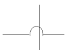
A. Wire crossing
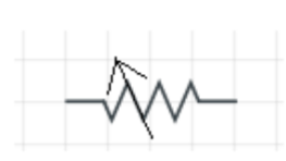
B. Rheostat
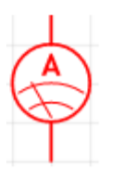
C. Ammeter
Answer
591.6k+ views
Hint: There are various electrical components that are used in the circuit diagrams. These are denoted by symbols on a paper and are often marked with their properties next to them. Each electrical component does a specific work.
Complete step-by-step solution:
There are various electrical symbols, which are used in circuit diagrams. These are denoted by symbols on a paper and are often marked with their properties next to them. Each electrical component does a specific work.
These are used to represent the circuit on a paper and often used to refer back.
The symbol of wire crossing is denoted as below, it is used to avoid the connection between two or more wires .i.e. it is used to jump a wire. This is useful when there are two or more wires, which are concentrated in the same region, but they are not connected to each other. Here, one wire crosses above or below the other wire, so that the connection is uninterrupted.

A rheostat, also called as variable resistance is denoted as below, it is used to the change .i.e. increase or decrease the resistance in the circuit. This is handy when it comes to certain experiments, where we need variable resistances or to understand how resistance affects other components of the circuit like current and voltage for example.

An ammeter is a device used to measure the current in the circuit and is denoted as below. An ammeter has minimum resistance to allow current to flow through it, this is because it is always connected in series with the circuit.

Note: An electronic symbol is used to denote various components like the wire, battery, resistor, transistor, and many more. Circuit symbols are used in circuit diagrams showing how a circuit is connected together. The actual layout of the components is usually quite different from the circuit diagram. These are standardized and accepted internationally. The main use of these is to simplify the circuit when drawn on a paper. It is much easier to denote the symbols than writing the words and also reduces language barriers.
Complete step-by-step solution:
There are various electrical symbols, which are used in circuit diagrams. These are denoted by symbols on a paper and are often marked with their properties next to them. Each electrical component does a specific work.
These are used to represent the circuit on a paper and often used to refer back.
The symbol of wire crossing is denoted as below, it is used to avoid the connection between two or more wires .i.e. it is used to jump a wire. This is useful when there are two or more wires, which are concentrated in the same region, but they are not connected to each other. Here, one wire crosses above or below the other wire, so that the connection is uninterrupted.

A rheostat, also called as variable resistance is denoted as below, it is used to the change .i.e. increase or decrease the resistance in the circuit. This is handy when it comes to certain experiments, where we need variable resistances or to understand how resistance affects other components of the circuit like current and voltage for example.

An ammeter is a device used to measure the current in the circuit and is denoted as below. An ammeter has minimum resistance to allow current to flow through it, this is because it is always connected in series with the circuit.

Note: An electronic symbol is used to denote various components like the wire, battery, resistor, transistor, and many more. Circuit symbols are used in circuit diagrams showing how a circuit is connected together. The actual layout of the components is usually quite different from the circuit diagram. These are standardized and accepted internationally. The main use of these is to simplify the circuit when drawn on a paper. It is much easier to denote the symbols than writing the words and also reduces language barriers.
Recently Updated Pages
Master Class 12 Economics: Engaging Questions & Answers for Success

Master Class 12 Physics: Engaging Questions & Answers for Success

Master Class 12 English: Engaging Questions & Answers for Success

Master Class 12 Social Science: Engaging Questions & Answers for Success

Master Class 12 Maths: Engaging Questions & Answers for Success

Master Class 12 Business Studies: Engaging Questions & Answers for Success

Trending doubts
Which are the Top 10 Largest Countries of the World?

What are the major means of transport Explain each class 12 social science CBSE

Draw a labelled sketch of the human eye class 12 physics CBSE

Why cannot DNA pass through cell membranes class 12 biology CBSE

Differentiate between insitu conservation and exsitu class 12 biology CBSE

Draw a neat and well labeled diagram of TS of ovary class 12 biology CBSE


