


Derive the expression for voltage gain of a transistor amplifier in CE configuration terms of the load resistance ${R_L}$, current gain ${\beta _\alpha }$ and input resistance. Explain why input and output voltages are in opposite phases.
Answer
579.3k+ views
Hint: Here, we will use Kirchhoff’s law to derive the expression for a voltage gain of a transistor amplifier in CE configuration. Also, keep in mind that an amplifier is a device that is used to increase the amplitude of the input signal.
Complete step by step solution:
As we know, the operation of a transistor as an amplifier is possible only if we fix its operating point in the middle of its active region.
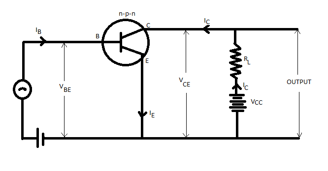
Now, we all know that amplifiers are used to amplify the alternating signals. Therefore, we will superimpose the ac input signal ${v_i}$ on ${v_{BB}}$. The output will be taken between the collector and ground.
Now, for an amplifier, we will take ${v_i} = 0$.
Hence, using Kirchhoff’s law to the output loop, we get
${V_{CC}} = {V_{CE}} + {I_C}{R_L}$
Now, using Kirchhoff’s law to the input loop, we get
${V_{BB}} = {V_{BE}} + {I_B}{R_B}$
Here, when ${V_i}$ is not zero, we get
${V_{BB}} + {v_i} = \left( {{V_{BE}} + \Delta {V_{BE}}} \right) + \left( {{I_B} + \Delta {I_B}} \right){R_B}$
Or ${V_{BB}} + {v_i} = {V_{BE}} + {I_B}{R_B} + \Delta {V_{BE}} + \Delta {I_B}{R_B}$
Here, the change in ${V_{BE}}$ can be related to the input resistance ${r_i}$ and the change in ${I_B}$ is given by
$\Delta {V_{BE}} = \Delta {I_B}{r_i}$
So, we will get
${V_{BB}} + {v_i} = {V_{BE}} + {I_B}{R_B} + \Delta {I_B}({R_B} + {r_i})$
Now, we will get the value of ${v_i}$ as
${V_{BB}} + {v_i} - {V_{BB}} = {V_{BE}} + {I_B}{R_B} + \Delta {I_B}({R_B} + {r_i}) - {V_{BE}} - {I_B}{R_B}$
$ \Rightarrow \,{v_i} = \Delta {I_B}({R_B} + {r_i})$
$ \Rightarrow \,{v_i} = r\Delta {I_B}$
Now, we can say that a change in ${I_B}$ causes a change in ${I_C}$. Therefore, we define will a new parameter ${\beta _{ac}}$ which is also similar to ${\beta _{dc}}$, as
${\beta _{ac}} = \dfrac{{\Delta {I_C}}}{{\Delta {I_B}}} = \dfrac{{{i_C}}}{{{i_B}}}$
This equation is also known as the current gain ${A_i}$. Usually, ${\beta _{ac}}$ remains close to ${\beta _{dc}}$ in the linear region of the output characteristics. Now, the change in ${I_C}$due to a change in ${I_B}$ leads to the change in ${V_{CE}}$ and the voltage drop across the resistor ${R_L}$, because ${V_{CC}}$ is fixed.
We can see the changes in the equation given below
$\Delta {V_{CC}} = \Delta {V_{CE}} + {R_L}\Delta {I_C}$
Here, if we consider $\Delta {V_{CC}} = 0$,
$\therefore \,\Delta {V_{CE}} = - {R_L}\Delta {I_C}$
Now, we know ${\beta _{ac}} = \dfrac{{\Delta {I_C}}}{{\Delta {I_B}}}$
Therefore, value of $\Delta {I_C}$from this equation to the above equation, we get
${v_0} = \Delta {V_{CE}} = - {\beta _{ac}}{R_L}\Delta {I_B}$
Therefore the voltage in the amplifier is given by
${A_v} = \dfrac{{{v_0}}}{{{v_i}}}$
$ \Rightarrow {A_v} = \dfrac{{\Delta {V_{CE}}}}{{r\Delta {I_B}}}$
$ \Rightarrow {A_v} = \dfrac{{ - {\beta _{ac}}{R_L}}}{r}$
Here, the negative sign shows that the output voltage is in the opposite phase to the input voltage.
Note: Consider that we apply an input signal voltage ${V_i}$ to the emitter-base circuit. We will observe that there will be a change in base current and collector current respectively.
Also, when the input voltage increases, the current through the base-circuit also increases. This will lead to a fall in the voltage between the collector and emitter terminals.
Complete step by step solution:
As we know, the operation of a transistor as an amplifier is possible only if we fix its operating point in the middle of its active region.
Now, we all know that amplifiers are used to amplify the alternating signals. Therefore, we will superimpose the ac input signal ${v_i}$ on ${v_{BB}}$. The output will be taken between the collector and ground.
Now, for an amplifier, we will take ${v_i} = 0$.
Hence, using Kirchhoff’s law to the output loop, we get
${V_{CC}} = {V_{CE}} + {I_C}{R_L}$
Now, using Kirchhoff’s law to the input loop, we get
${V_{BB}} = {V_{BE}} + {I_B}{R_B}$
Here, when ${V_i}$ is not zero, we get
${V_{BB}} + {v_i} = \left( {{V_{BE}} + \Delta {V_{BE}}} \right) + \left( {{I_B} + \Delta {I_B}} \right){R_B}$
Or ${V_{BB}} + {v_i} = {V_{BE}} + {I_B}{R_B} + \Delta {V_{BE}} + \Delta {I_B}{R_B}$
Here, the change in ${V_{BE}}$ can be related to the input resistance ${r_i}$ and the change in ${I_B}$ is given by
$\Delta {V_{BE}} = \Delta {I_B}{r_i}$
So, we will get
${V_{BB}} + {v_i} = {V_{BE}} + {I_B}{R_B} + \Delta {I_B}({R_B} + {r_i})$
Now, we will get the value of ${v_i}$ as
${V_{BB}} + {v_i} - {V_{BB}} = {V_{BE}} + {I_B}{R_B} + \Delta {I_B}({R_B} + {r_i}) - {V_{BE}} - {I_B}{R_B}$
$ \Rightarrow \,{v_i} = \Delta {I_B}({R_B} + {r_i})$
$ \Rightarrow \,{v_i} = r\Delta {I_B}$
Now, we can say that a change in ${I_B}$ causes a change in ${I_C}$. Therefore, we define will a new parameter ${\beta _{ac}}$ which is also similar to ${\beta _{dc}}$, as
${\beta _{ac}} = \dfrac{{\Delta {I_C}}}{{\Delta {I_B}}} = \dfrac{{{i_C}}}{{{i_B}}}$
This equation is also known as the current gain ${A_i}$. Usually, ${\beta _{ac}}$ remains close to ${\beta _{dc}}$ in the linear region of the output characteristics. Now, the change in ${I_C}$due to a change in ${I_B}$ leads to the change in ${V_{CE}}$ and the voltage drop across the resistor ${R_L}$, because ${V_{CC}}$ is fixed.
We can see the changes in the equation given below
$\Delta {V_{CC}} = \Delta {V_{CE}} + {R_L}\Delta {I_C}$
Here, if we consider $\Delta {V_{CC}} = 0$,
$\therefore \,\Delta {V_{CE}} = - {R_L}\Delta {I_C}$
Now, we know ${\beta _{ac}} = \dfrac{{\Delta {I_C}}}{{\Delta {I_B}}}$
Therefore, value of $\Delta {I_C}$from this equation to the above equation, we get
${v_0} = \Delta {V_{CE}} = - {\beta _{ac}}{R_L}\Delta {I_B}$
Therefore the voltage in the amplifier is given by
${A_v} = \dfrac{{{v_0}}}{{{v_i}}}$
$ \Rightarrow {A_v} = \dfrac{{\Delta {V_{CE}}}}{{r\Delta {I_B}}}$
$ \Rightarrow {A_v} = \dfrac{{ - {\beta _{ac}}{R_L}}}{r}$
Here, the negative sign shows that the output voltage is in the opposite phase to the input voltage.
Note: Consider that we apply an input signal voltage ${V_i}$ to the emitter-base circuit. We will observe that there will be a change in base current and collector current respectively.
Also, when the input voltage increases, the current through the base-circuit also increases. This will lead to a fall in the voltage between the collector and emitter terminals.
Recently Updated Pages
Master Class 12 Economics: Engaging Questions & Answers for Success
Master Class 12 Physics: Engaging Questions & Answers for Success
Master Class 12 English: Engaging Questions & Answers for Success
Master Class 12 Social Science: Engaging Questions & Answers for Success
Master Class 12 Maths: Engaging Questions & Answers for Success
Master Class 12 Business Studies: Engaging Questions & Answers for Success
Trending doubts
Which are the Top 10 Largest Countries of the World?
What are the major means of transport Explain each class 12 social science CBSE
Draw a labelled sketch of the human eye class 12 physics CBSE
Why cannot DNA pass through cell membranes class 12 biology CBSE
Differentiate between insitu conservation and exsitu class 12 biology CBSE
Draw a neat and well labeled diagram of TS of ovary class 12 biology CBSE