


How Does a Resonance Column Tube Work in Measuring Sound?
The resonance column tube experiment is a classic method for exploring standing waves within an air column and directly measuring the speed of sound in air using resonant frequencies. Its core idea is that when the length of an air column matches certain resonance conditions with a vibrating tuning fork, sound intensity sharply increases due to constructive interference of reflected waves.
Understanding Resonance in an Air Column Tube
When a tuning fork is struck and held above the open end of a vertically arranged tube, the sound waves it produces enter the tube, reflect from the water surface at the closed end, and interact with newly incoming waves. If the length of air column above water supports a standing wave pattern, resonance is achieved, marked by a loud, clear sound.
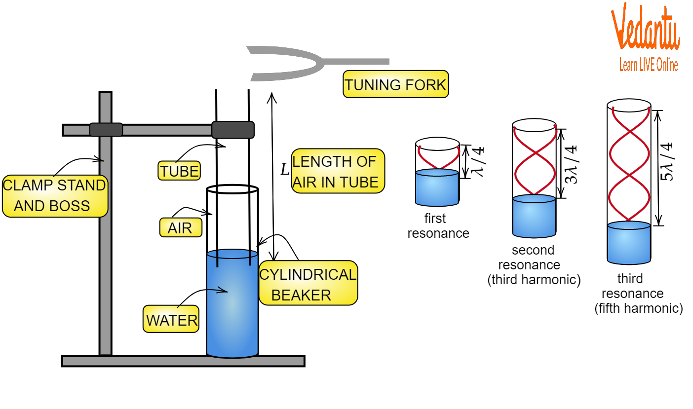
A resonance column tube essentially behaves as a pipe closed at one end (where the water is) and open at the other. The physics here is characterized by the formation of nodes (no displacement) at the water surface and antinodes (maximum displacement) at the open top. This fundamental boundary condition is crucial for calculating both wavelength and frequency relationships inside the tube.
Resonant Standing Waves: Physical Basis and Conditions
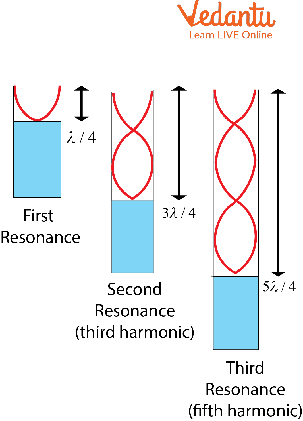
For resonance to occur, the column length must support a standing wave with a node at the closed end and an antinode at the open end. In a closed-open system, resonance happens at lengths where the air column equals odd multiples of a quarter-wavelength. Mathematically, $L = (2n-1)\dfrac{\lambda}{4}$ with $n=1,2,3...$ for successive resonances.
A key observation is that the first resonance length ($L_1$) corresponds to the fundamental mode ($n=1$), while the second ($L_2$) aligns with the next possible odd multiple. The difference $L_2-L_1$ gives half the sound wavelength in air, which is vital for calculating the speed of sound from experimental measurements.
Experimental Setup: Components and Measurement Sequence
The experimental setup uses a long vertical tube, open at the top and immersed in a water reservoir at the bottom. The length of the air column can be adjusted by raising or lowering the water level, enabling precise control over the resonance condition for a given tuning fork frequency.
- Resonance tube: glass, one end open, other end water-closed
- Adjustable water reservoir for moving the water level
- Tuning fork with known frequency (usually 512 Hz)
- Meter scale to measure resonance length
To perform the measurement, strike the tuning fork, hold it above the tube, and slowly alter the column length. Listen carefully for a moment of sharply increased sound—this is a resonance point. Measure the air column length at this moment, then repeat for higher resonances.
Calculating Speed of Sound: Resonance Column Tube Formula
Consider successive resonance lengths $L_1$ and $L_2$. Since each resonance point adds half a wavelength ($\dfrac{\lambda}{2}$) to the effective column length, we write: $\lambda = 2 (L_2 - L_1)$. If end correction $e$ is included to account for the antinode forming slightly above the tube's opening, the refined formula is $\lambda = 2 \left[(L_2 + e) - (L_1 + e)\right] = 2 (L_2 - L_1)$.
The speed of sound $v$ in air is then given by $v = f \lambda$, where $f$ is the frequency of the tuning fork. This approach directly links the measurable column lengths with physical parameters of wave propagation.
| Physical Quantity | Symbol / Formula |
|---|---|
| Wavelength of sound | $\lambda = 2(L_2 - L_1)$ |
| Speed of sound | $v = f \lambda$ |
| End correction | $e \approx 0.6 \times r$ |
Use a precise millimeter scale and ensure the tube remains vertical to avoid errors. For detailed worked problems and stepwise calculations, see our full guide on Resonance Column Tube.
Role of End Correction in Real Measurements
In reality, the position of the antinode is slightly higher than the tube's rim, making the effective length of air column longer than its measured value. This systematic error is corrected by adding the end correction ($e$), typically calculated as approximately $0.6$ times the tube's radius. Always apply this tweak to enhance result accuracy.
Comparison: Resonance Column vs. Organ Pipes
While the resonance tube acts as a closed-end organ pipe, it is important to distinguish it from pipes open at both ends, which generate both odd and even harmonics and differ in resonance conditions. Both systems, however, rely on standing wave formation.
| Aspect | Resonance Column Tube |
|---|---|
| Ends | One open, one closed (water) |
| Harmonics Observed | Odd only (1st, 3rd…) |
| Application | Measure speed of sound |
More about the connection between resonance tubes and sound production in music instruments is explained in our article on Properties of Sound.
Experimental Limitations and Error Sources
- Temperature and humidity affect speed of sound values
- Misreading the water level introduces parallax error
- Tuning fork not struck perpendicularly reduces resonance sharpness
- Not applying end correction leads to systematic over- or underestimation
Repeating the process with various fork frequencies and calculating average values reduces random errors, leading to a more reliable determination by the resonance column method.
Exploring Connected Wave Phenomena Further
The resonance column experiment connects directly to broader topics like wave theory and oscillations, and is essential background for understanding natural and forced oscillations, echo, and musical instruments. Dive deeper through our modules on Oscillations and Waves and discover further implications in Application of Echo.
For learners seeking an interactive approach, resonance tube simulation tools and calculators can visually demonstrate how air column length and frequency interplay to create sharp resonance. This experience enhances conceptual clarity, paving the way for advanced study and practical exam success on topics allied to Wave Motion and Sound Waves.


FAQs on Understanding the Resonance Column Tube: Principles and Applications
1. What is a resonance column experiment?
The resonance column experiment is a laboratory method to determine the speed of sound in air using a tube partially filled with water. The experiment is based on the resonance phenomenon, where a standing wave is produced. The steps involved are:
- A resonance tube is set vertically with water at the bottom.
- A tuning fork of known frequency is struck and held above the tube mouth.
- The length of the air column is adjusted, either by raising or lowering the water level, until resonance (loudest sound) is heard.
- Key measurements allow calculation of the speed of sound in air.
2. How does a resonance column tube work?
A resonance column tube works by creating standing sound waves in an air column above water, which resonate at specific lengths. This happens when:
- A tuning fork of known frequency is placed at the tube's opening.
- The air column’s length is adjusted by changing the water level.
- Resonance occurs at lengths where the column matches odd multiples of quarter wavelengths.
3. What is the formula used in the resonance column experiment?
The main formula used in the resonance column experiment is:
v = 4lf
Where:
- v = speed of sound in air
- l = length of air column at resonance (in meters)
- f = frequency of the tuning fork (in Hz)
4. What are resonance and standing waves?
Resonance occurs when the frequency of an external force matches the natural frequency of a system, producing maximum vibration. Standing waves are patterns formed when two waves of the same frequency travel in opposite directions and interfere.
- In the resonance column, standing waves are set up in air, making resonance possible.
- Nodes and antinodes form at specific locations, critical for measurement.
5. How do you find the speed of sound using a resonance column tube?
The speed of sound in air can be found by measuring the length of the resonating air column and using the tuning fork’s frequency. Steps include:
- Strike a known-frequency tuning fork and hold it above the resonance column.
- Adjust water level to find resonance length (l).
- Apply the formula: v = 4lf.
6. What are the sources of error in the resonance column experiment?
Common errors in the resonance column experiment can affect the accuracy of results. Key sources include:
- End correction: Due to the pipe’s open end, actual column length is slightly longer than measured.
- Inaccurate measurement of resonance length.
- Incorrect frequency of tuning fork.
- Temperature and humidity variations affecting sound speed.
7. What is end correction in the resonance tube experiment?
End correction is an adjustment made to account for the displacement of the antinode just above the open end of the tube, not exactly at the tube’s edge.
- The effective length of the air column is slightly more than the directly measured value.
- Typically, end correction (e) is added, often calculated as about 0.6 × radius of the tube.
- The corrected length is: l_{effective} = l_{measured} + e
8. What are the applications of resonance column tube?
The resonance column tube has several scientific and educational applications, including:
- Measuring speed of sound in air for lab work.
- Demonstrating standing waves and resonance phenomena.
- Verifying theoretical relationships in acoustics and wave physics.
- Training in experimental physics methods.
9. Why is water used in the resonance column experiment?
Water is used to adjust the air column length easily inside the tube and helps determine the point of resonance accurately.
- Raising or lowering the water level changes the effective length for resonance.
- It provides a quick, visual way to find resonance position.
10. Define resonance in physics with an example.
Resonance in physics refers to the condition when a system oscillates with maximum amplitude at a specific frequency called the natural frequency.
- Example: Striking a tuning fork over a resonance column tube causes the air column to vibrate at its resonant frequency, creating a loud sound.
11. What observations are made during the resonance column experiment?
During the resonance column experiment, key observations include:
- The air column length at which the loudest sound (resonance) occurs.
- Frequency of the tuning fork used.
- Measurements for calculating end correction.
12. Can resonance occur at more than one position in a resonance tube?
Yes, resonance can occur at multiple positions called harmonics or overtones in a resonance tube.
- The fundamental resonance is at the shortest possible resonant air column (first harmonic).
- Subsequent longer columns produce higher-order resonances (third, fifth, etc.).