


How Does an RC Circuit Charge and Discharge?
An RC circuit is a fundamental electrical circuit consisting of a resistor and a capacitor connected in series or parallel. RC circuits are crucial for understanding charging and discharging behaviors of capacitors, which are important in electronic devices and JEE Main Physics. This article provides a clear explanation of RC circuit concepts, equations, analysis methods, and solved examples for JEE Main.
Basic Structure and Function of an RC Circuit
An RC circuit contains a resistor ($R$) and a capacitor ($C$) connected in a specific arrangement. When a voltage source is applied, the circuit exhibits time-dependent behavior as the capacitor charges or discharges through the resistor.
The resistor controls the flow of electric current, while the capacitor stores electric charge. The rate of charging or discharging in the circuit is governed by both $R$ and $C$ values. For foundational concepts, refer to RC Circuit Overview.
Charging of a Capacitor in an RC Circuit
When a capacitor is connected in series with a resistor and a DC voltage source, it starts charging. The charging process is exponential and does not occur instantly. The current and charge change with time until the capacitor is fully charged.
The charge on the capacitor at any time $t$ is given by the equation:
$q = q_0\left[1 - e^{-t/RC}\right]$
Here, $q_0 = C\varepsilon$ is the maximum charge, where $\varepsilon$ is the applied emf. The current in the circuit at any time $t$ is:
$I = I_0 e^{-t/RC}$
$I_0$ is the initial current, given by $I_0 = \dfrac{\varepsilon}{R}$. The charging is considered nearly complete after a time interval much greater than $RC$.
RC Time Constant and Its Importance
The product $RC$ is known as the time constant, denoted by $\tau$. It determines the rate at which the capacitor charges or discharges. The time constant is measured in seconds and is a key parameter in RC circuits.
After a time interval equal to one time constant $(t = RC)$, the charge on the capacitor reaches about 63% of its maximum value. The current falls to approximately 37% of its initial value.
| Parameter | Value at $t = RC$ |
|---|---|
| Charge on Capacitor ($q$) | $0.63q_0$ |
| Current ($I$) | $0.37I_0$ |
Derivation of Charging Formulas Using Kirchhoff's Law
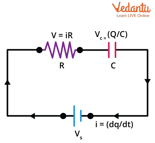
Kirchhoff’s Voltage Law is applied to analyze the RC circuit during charging. The law states that the sum of voltages in a closed loop equals zero. For a series RC circuit, the equation is written as:
$\varepsilon - iR - \dfrac{q}{C} = 0$
Rearranging and integrating this differential equation yields the standard charging equation for both charge and current in the circuit. For a detailed understanding of capacitors' role, refer to Explore Capacitors.
Discharging of a Capacitor in an RC Circuit
When the charged capacitor is disconnected from the emf source and allowed to discharge through the resistor, the process also follows an exponential law. The current and charge decrease over time as the capacitor releases stored energy.
The charge remaining on the capacitor at time $t$ during discharge is:
$q = q_0 e^{-t/RC}$
The current in the discharging circuit is:
$I = -I_0 e^{-t/RC}$
The negative sign indicates that the current direction is opposite to that of the charging current. For more on electric current flow, see Electric Current Fundamentals.
Voltage Across Resistor and Capacitor
The voltage across the resistor and capacitor varies with time. During charging:
- Voltage across capacitor: $V_C = \varepsilon (1 - e^{-t/RC})$
- Voltage across resistor: $V_R = \varepsilon e^{-t/RC}$
During discharging, both voltages decrease exponentially, following the respective exponential equations for $q$ and $I$. For more on resistance behavior, refer to Ohm's Law and Resistance.
Energy Considerations and Heat Dissipation
The energy supplied by the battery in the RC circuit is partly stored in the capacitor and partly dissipated as heat in the resistor. The heat dissipated equals $ \dfrac{1}{2} C \varepsilon^2 $ after a long time for a complete charging process.
| Energy Form | Expression |
|---|---|
| Capacitor Stored Energy | $\dfrac{1}{2} C \varepsilon^2$ |
| Heat Dissipated | $\dfrac{1}{2} C \varepsilon^2$ |
Time Constant Calculation in Complex RC Circuits
In circuits with multiple resistors and capacitors, the time constant may be calculated using Thevenin’s theorem. This involves reducing the circuit to a single equivalent resistor and using the same capacitor. The effective time constant is $\tau = R_{\text{eff}} C$.
To analyze such circuits, first remove the capacitor and calculate the resistance seen across its terminals, then multiply by the capacitance to determine $\tau$. For circuit simplification methods, refer to Circuit Solving Techniques.
Analysis of Complex RC Networks
For RC circuits with multiple branches, Kirchhoff's Laws are employed to write equations for each loop. These equations are then solved to find the time-dependent charge and current in each branch. For advanced RC circuit arrangements, combine resistors using series and parallel rules before applying the RC equations.
RC Circuit Equations and Formulas Summary
The following key equations are used in RC circuit analysis:
- Charge during charging: $q = C\varepsilon\left[1 - e^{-t/RC}\right]$
- Current during charging: $I = \dfrac{\varepsilon}{R} e^{-t/RC}$
- Charge during discharging: $q = q_0 e^{-t/RC}$
- Current during discharging: $I = -\dfrac{q_0}{RC} e^{-t/RC}$
- Time constant: $\tau = RC$
Solved Examples: RC Circuits
1. A $10\,\mu\text{F}$ capacitor is charged through a $2\,\text{k}\Omega$ resistor by a $20\,\text{V}$ battery. Calculate the charge after one time constant.
Time constant, $\tau = RC = (2 \times 10^3)(10 \times 10^{-6}) = 0.02\,\text{s}$. Maximum charge, $q_0 = C\varepsilon = 10 \times 10^{-6} \times 20 = 2 \times 10^{-4}\,\text{C}$. After one $\tau$, $q = q_0(1 - e^{-1}) \approx 0.63q_0 = 1.26 \times 10^{-4}\,\text{C}$.
2. A capacitor of $5\,\mu\text{F}$ with initial charge $15\,\mu\text{C}$ is discharged through a $10\,\Omega$ resistor. Find the remaining charge after $50\,\mu\text{s}$.
$\tau = RC = 10 \times 5 \times 10^{-6} = 50\,\mu\text{s}$. After $t = \tau$, $q = q_0 e^{-1} \approx 15\,\mu\text{C} \times 0.37 = 5.55\,\mu\text{C}$.
RC Circuit Applications and Further Study
RC circuits are widely used in timing devices, filtering operations, and analog circuits. Understanding RC circuit analysis is essential for physics problem-solving and lays the foundation for topics involving AC circuits. For topics related to inductor behavior, see Understanding Inductors.
FAQs on Understanding RC Circuits: How Resistors and Capacitors Work Together
1. What is an RC circuit?
An RC circuit is an electrical circuit consisting of a resistor (R) and a capacitor (C) connected in series or parallel. It is widely used to filter signals, delay voltage changes, and produce timing effects in electronics. Key characteristics include:
- Contains one resistor and one capacitor
- Responds to alternating current (AC) and direct current (DC)
- Exhibits a time-dependent charging and discharging behavior of the capacitor
2. What is the time constant in an RC circuit?
The time constant of an RC circuit, denoted by τ (tau), represents the time required for the voltage across the capacitor to rise (or fall) to about 63% of its final value during charging or discharging. It is calculated as:
- τ = R × C
- R = resistance in ohms (Ω)
- C = capacitance in farads (F)
3. How does an RC circuit behave during charging and discharging?
During charging, the capacitor's voltage increases exponentially towards the supply voltage, while during discharging, it decreases exponentially toward zero. Key points include:
- Charging: Current and voltage change over time, not instantly
- Discharging: Capacitor loses its stored charge exponentially
- Mathematically described by V(t) = V₀ × (1 - e−t/RC) for charging and V(t) = V₀ × e−t/RC for discharging
4. What are the applications of RC circuits?
RC circuits are used in many electronic devices due to their ability to filter, delay, or shape signals. Common applications include:
- Low-pass and high-pass filters
- Timing circuits in oscillators and timers
- Coupling and decoupling capacitors in amplifiers
- Integrators and differentiators in signal processing
5. How do you calculate the voltage across the capacitor in an RC circuit?
The voltage across the capacitor in an RC circuit is calculated using time-dependent exponential formulas:
- For charging: VC(t) = V0[1 – exp(–t/RC)]
- For discharging: VC(t) = V0exp(–t/RC)
6. What is the function of the resistor and capacitor in an RC circuit?
The resistor controls the rate at which the capacitor charges or discharges, while the capacitor stores and releases electrical energy. Together, they create a time-dependent voltage change.
- Resistor limits current flow
- Capacitor stores electric charge
- Combination determines the circuit’s time constant (τ)
7. Why are RC circuits called filters?
RC circuits are called filters because they allow certain frequency signals to pass while blocking others, working as either low-pass or high-pass filters:
- Low-pass RC filters allow low-frequency signals and block high frequencies
- High-pass RC filters allow high-frequency signals and block low frequencies
- They are widely used in audio and communication systems
8. What happens to the current in an RC circuit over time?
The current in an RC circuit decreases exponentially as the capacitor charges, and also falls rapidly to zero during discharging. Specifically:
- At t=0, current is highest during charging
- Current approaches zero as capacitor gets fully charged or discharged
- Obeys I(t) = (V0/R) × exp(–t/RC) for charging/discharging
9. How does the time constant affect charging and discharging in an RC circuit?
The time constant (τ = RC) determines the speed of charging and discharging. A larger τ means slower responses, while a smaller τ means faster reactions:
- After 1τ, capacitor charges to ~63% of its maximum voltage
- After 5τ, charging or discharging is almost complete (>99%)
- Time constant is a fundamental measure in RC circuit analysis
10. What is the equation for charging a capacitor in an RC circuit?
The charging equation for a capacitor in an RC circuit is:
- VC(t) = V0[1 – e–t/RC]
11. What is the significance of the cutoff frequency in an RC filter circuit?
The cutoff frequency in an RC filter is the frequency at which the output drops to 70.7% of the input (–3 dB point). It divides pass-band and stop-band frequencies in filters:
- Calculated as fc = 1/(2πRC)
- Below/above this frequency, attenuation increases rapidly depending on filter type
- Used in signal processing to separate or suppress unwanted frequencies
12. What are the differences between series and parallel RC circuits?
Series RC circuits connect the resistor and capacitor in sequence, while in parallel RC circuits, they are connected across the same voltage source. The main differences include:
- Series: Same current flows through both components, voltage divides
- Parallel: Same voltage across both, current divides
- Frequency response and filtering functions vary