


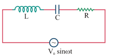
Impedance, reactance and average power in series LCR,LR,LC or CR circuit.
Derive an expression for the impedance of a series LCR circuit. Use a phasor diagram.
Answer
543.6k+ views
Hint: The above question will have the involvement of three passive elements LCR which are Inductor, capacitor and resistor.
The three elements are connected in series in the circuit which will have a few properties in common.
Impedance of a circuit is equal to the ratio of the total voltage across the elements connected and the total current through the circuit.
Using the properties of the series LCR circuit we will solve the given problem.
Complete answer:
As per the series connection we have the phasor diagram of the circuit is
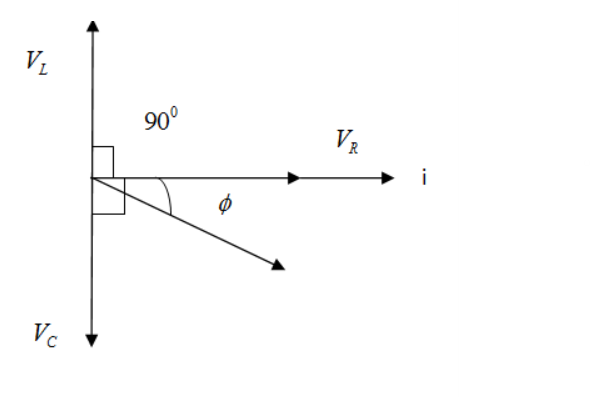
By using the phasor diagram we have;
Voltage across Resistor is ${V_R}$ , Voltage across capacitor is ${V_C}$and Voltage across inductor is ${V_L}$.
We have drawn the phasor diagram keeping ${V_L}$greater than ${V_C}$, then ${V_L}$- ${V_C}$;
Total voltage across the circuit is;
$ \Rightarrow V = \sqrt {{V_R}^2 + {{({V_L} - {V_C})}^2}} $ .................1
Total current through the circuit is $i$
${V_R}$= i R , ${V_C}$= i ${X_C}$ , ${V_L}$= i ${X_L}$ ................2
We can replace the voltages in equation 1 by the values given in equation 2
$ \Rightarrow V = \sqrt {{{(iR)}^2} + ({{(i{X_L})}^2} - {{(i{X_C})}^2}} $
Impedance is given as;
$ \Rightarrow Z = \dfrac{{\sqrt {{{(iR)}^2} + ({{(i{X_L})}^2} - {{(i{X_C})}^2}} }}{i}$
We will take out i common from the numerator and denominator;
$ \Rightarrow Z = \dfrac{{i\sqrt {{{(R)}^2} + {{({X_L})}^2} - {{({X_C})}^2}} }}{i}$(cancel i )
$ \Rightarrow Z = \sqrt {{{(R)}^2} + {{({X_L})}^2} - {{({X_C})}^2}} $(Impedance of the series LCR circuit)
In the similar manner impedance or reactance of the LC,RC,RL circuit will be;
${Z_{LR}} = \sqrt {{R^2} + {X_L}^2} $ (Impedance of RL circuit)
${Z_{RC}} = \sqrt {{R^2} + {X_L}^2} $(Impedance of RC circuit)
${Z_{LC}} = \sqrt {{{({X_L} - {X_C})}^2}} $(Impedance of LC circuit)
Average power of the circuit is being calculated as;
Instantaneous values of the current and voltages are given by;
$V = {V_0}\sin \omega t$..............3 and $I = {I_0}\sin (\omega t + \phi )$ .............4
Instantaneous power is given by;
$P = VI$
On multiplying the equation 3 and 4
We get;
$ \Rightarrow {V_0}\sin \omega t \times {I_0}\sin (\omega t + \phi )$................5
On further solving the equation 5 we get;
$P = \dfrac{1}{2}{V_0}{I_0}\cos \phi $
Note:
Series LCR circuit has applications in radio and communication engineering. They can be used to select a certain narrow range of frequencies from the total spectrum of ambient radio waves. For example AM/FM radio along with analog turners use a RLC circuit to tune a radio frequency.
The three elements are connected in series in the circuit which will have a few properties in common.
Impedance of a circuit is equal to the ratio of the total voltage across the elements connected and the total current through the circuit.
Using the properties of the series LCR circuit we will solve the given problem.
Complete answer:
As per the series connection we have the phasor diagram of the circuit is
By using the phasor diagram we have;
Voltage across Resistor is ${V_R}$ , Voltage across capacitor is ${V_C}$and Voltage across inductor is ${V_L}$.
We have drawn the phasor diagram keeping ${V_L}$greater than ${V_C}$, then ${V_L}$- ${V_C}$;
Total voltage across the circuit is;
$ \Rightarrow V = \sqrt {{V_R}^2 + {{({V_L} - {V_C})}^2}} $ .................1
Total current through the circuit is $i$
${V_R}$= i R , ${V_C}$= i ${X_C}$ , ${V_L}$= i ${X_L}$ ................2
We can replace the voltages in equation 1 by the values given in equation 2
$ \Rightarrow V = \sqrt {{{(iR)}^2} + ({{(i{X_L})}^2} - {{(i{X_C})}^2}} $
Impedance is given as;
$ \Rightarrow Z = \dfrac{{\sqrt {{{(iR)}^2} + ({{(i{X_L})}^2} - {{(i{X_C})}^2}} }}{i}$
We will take out i common from the numerator and denominator;
$ \Rightarrow Z = \dfrac{{i\sqrt {{{(R)}^2} + {{({X_L})}^2} - {{({X_C})}^2}} }}{i}$(cancel i )
$ \Rightarrow Z = \sqrt {{{(R)}^2} + {{({X_L})}^2} - {{({X_C})}^2}} $(Impedance of the series LCR circuit)
In the similar manner impedance or reactance of the LC,RC,RL circuit will be;
${Z_{LR}} = \sqrt {{R^2} + {X_L}^2} $ (Impedance of RL circuit)
${Z_{RC}} = \sqrt {{R^2} + {X_L}^2} $(Impedance of RC circuit)
${Z_{LC}} = \sqrt {{{({X_L} - {X_C})}^2}} $(Impedance of LC circuit)
Average power of the circuit is being calculated as;
Instantaneous values of the current and voltages are given by;
$V = {V_0}\sin \omega t$..............3 and $I = {I_0}\sin (\omega t + \phi )$ .............4
Instantaneous power is given by;
$P = VI$
On multiplying the equation 3 and 4
We get;
$ \Rightarrow {V_0}\sin \omega t \times {I_0}\sin (\omega t + \phi )$................5
On further solving the equation 5 we get;
$P = \dfrac{1}{2}{V_0}{I_0}\cos \phi $
Note:
Series LCR circuit has applications in radio and communication engineering. They can be used to select a certain narrow range of frequencies from the total spectrum of ambient radio waves. For example AM/FM radio along with analog turners use a RLC circuit to tune a radio frequency.
Recently Updated Pages
Master Class 12 Economics: Engaging Questions & Answers for Success
Master Class 12 Physics: Engaging Questions & Answers for Success
Master Class 12 English: Engaging Questions & Answers for Success
Master Class 12 Social Science: Engaging Questions & Answers for Success
Master Class 12 Maths: Engaging Questions & Answers for Success
Master Class 12 Business Studies: Engaging Questions & Answers for Success
Trending doubts
Which are the Top 10 Largest Countries of the World?
What are the major means of transport Explain each class 12 social science CBSE
Draw a labelled sketch of the human eye class 12 physics CBSE
Why cannot DNA pass through cell membranes class 12 biology CBSE
Differentiate between insitu conservation and exsitu class 12 biology CBSE
Draw a neat and well labeled diagram of TS of ovary class 12 biology CBSE