


If the power factor in a circuit is unity, then the impedance of the circuit is
A. Inductive
B. Capacitive
C. Partially inductive and partially capacitive
D. Resistive
Answer
626.4k+ views
Hint: It is important to know the definition of power factor for solving this question. The power factor is defined as the ratio of the real power absorbed by the load to the apparent power flowing in the circuit. It is a dimensionless number ranging from -1 to +1.
Complete step by step answer:
Consider the following LRC circuit connected to an AC source of voltage $V = {V_0}\sin \omega t$ where $\omega $ is the angular frequency, $\omega = 2\pi f$:
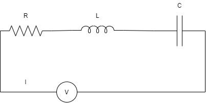
The impedance, Z is defined as the resistance offered to the flow of alternating current I through the entire circuit. Here, in the figure, the impedance Z is the vector sum of the reactances of the individual resistance, inductor, and the capacitor.
Capacitive reactance, ${X_c} = \dfrac{1}{{\omega C}}$
Inductive reactance, ${X_L} = \omega L$
Resistance is $R$.
Impedance, $Z = R + \left( {{X_L} - {X_C}} \right)$
These quantities cannot be added in a scalar manner since they have different phases. We have to add these values through vector addition by drawing the impedance triangle with $\phi $ as the phase angle.
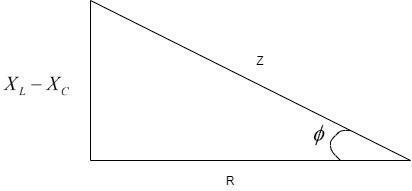
Thus, we can see that the Z is the vector sum of the reactance and the resistance as the triangle.
${Z^2} = {R^2} + {\left( {{X_L} - {X_C}} \right)^2}$
Here, the value of $\cos \phi $ is called the power factor, which gives the ratio of the real power that the load absorbs and the apparent power that the circuit absorbs.
Power factor = Real power / Apparent power
Power factor = $\dfrac{{{I^2}R}}{{{I^2}Z}}$
Therefore, from the figure, we can write that, Power factor = $\dfrac{R}{Z} = \cos \phi $
For the power factor to be one, $\cos \phi = 1$
where, $R = Z$
Substituting in the impedance equation, we get –
$
{Z^2} = {R^2} + {\left( {{X_L} - {X_C}} \right)^2} \\
\Rightarrow {R^2} = {R^2} + {\left( {{X_L} - {X_C}} \right)^2} \\
\Rightarrow {\left( {{X_L} - {X_C}} \right)^2} = 0 \\
\therefore {X_L} = {X_C} \\
$
Here, we see that inductive and capacitive reactance is equal and thus, they cancel out each other. When they cancel out, only the resistance stands out.
Thus, the circuit where only resistance acts is called a resistive circuit. Hence, the correct option is Option D.
Note:
Some students may get confused as to why we have taken $\left( {{X_L} - {X_C}} \right)$ and not $\left( {{X_C} - {X_L}} \right)$. This arises from the fact that in this problem, the circuit is assumed generally, to be inductive. However, in the problem, if we have a capacitive circuit, we should consider the expression $\left( {{X_C} - {X_L}} \right)$.
Complete step by step answer:
Consider the following LRC circuit connected to an AC source of voltage $V = {V_0}\sin \omega t$ where $\omega $ is the angular frequency, $\omega = 2\pi f$:
The impedance, Z is defined as the resistance offered to the flow of alternating current I through the entire circuit. Here, in the figure, the impedance Z is the vector sum of the reactances of the individual resistance, inductor, and the capacitor.
Capacitive reactance, ${X_c} = \dfrac{1}{{\omega C}}$
Inductive reactance, ${X_L} = \omega L$
Resistance is $R$.
Impedance, $Z = R + \left( {{X_L} - {X_C}} \right)$
These quantities cannot be added in a scalar manner since they have different phases. We have to add these values through vector addition by drawing the impedance triangle with $\phi $ as the phase angle.
Thus, we can see that the Z is the vector sum of the reactance and the resistance as the triangle.
${Z^2} = {R^2} + {\left( {{X_L} - {X_C}} \right)^2}$
Here, the value of $\cos \phi $ is called the power factor, which gives the ratio of the real power that the load absorbs and the apparent power that the circuit absorbs.
Power factor = Real power / Apparent power
Power factor = $\dfrac{{{I^2}R}}{{{I^2}Z}}$
Therefore, from the figure, we can write that, Power factor = $\dfrac{R}{Z} = \cos \phi $
For the power factor to be one, $\cos \phi = 1$
where, $R = Z$
Substituting in the impedance equation, we get –
$
{Z^2} = {R^2} + {\left( {{X_L} - {X_C}} \right)^2} \\
\Rightarrow {R^2} = {R^2} + {\left( {{X_L} - {X_C}} \right)^2} \\
\Rightarrow {\left( {{X_L} - {X_C}} \right)^2} = 0 \\
\therefore {X_L} = {X_C} \\
$
Here, we see that inductive and capacitive reactance is equal and thus, they cancel out each other. When they cancel out, only the resistance stands out.
Thus, the circuit where only resistance acts is called a resistive circuit. Hence, the correct option is Option D.
Note:
Some students may get confused as to why we have taken $\left( {{X_L} - {X_C}} \right)$ and not $\left( {{X_C} - {X_L}} \right)$. This arises from the fact that in this problem, the circuit is assumed generally, to be inductive. However, in the problem, if we have a capacitive circuit, we should consider the expression $\left( {{X_C} - {X_L}} \right)$.
Recently Updated Pages
Master Class 12 Business Studies: Engaging Questions & Answers for Success
Master Class 12 Chemistry: Engaging Questions & Answers for Success
Master Class 12 Biology: Engaging Questions & Answers for Success
Class 12 Question and Answer - Your Ultimate Solutions Guide
Master Class 11 English: Engaging Questions & Answers for Success
Master Class 11 Social Science: Engaging Questions & Answers for Success
Trending doubts
Which are the Top 10 Largest Countries of the World?
Draw a labelled sketch of the human eye class 12 physics CBSE
The end of compass needle which points towards north class 12 physics CBSE
Differentiate between homogeneous and heterogeneous class 12 chemistry CBSE
Why is the cell called the structural and functional class 12 biology CBSE
When was the first election held in India a 194748 class 12 sst CBSE