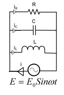
A resistor of resistance R, capacitor of capacitance C and inductor of inductance L are connected in parallel to AC power source of voltage\[{{E}_{0}}\sin \omega t\].The maximum current through the resistance is half of the maximum current through the power source. Then value of R is
\[\begin{align}
& A)\dfrac{\sqrt{3}}{\left| \omega C-\dfrac{1}{\omega L} \right|} \\
& B)\sqrt{3}\left| \dfrac{1}{\omega L}-\omega L \right| \\
& C)\sqrt{5}\left| \dfrac{1}{\omega L}-\omega L \right| \\
& D)None \\
\end{align}\]
Answer
534k+ views
Hint: Since in this question , all components are parallel to the voltage source so firstly current gets divided into three branches and sum of current of all branches gives the total current from the power source. Here, the maximum current equation has resistance R only while for power source current all three components are active.
Complete answer:
Here in the given circuit Resistance R, Capacitor C and inductor L are connected in parallel to AC power source of voltage\[{{E}_{0}}\sin \omega t\].
Let i be the current drawn from the AC power source and we know that in parallel circuit current gets divided into different branches.
Let us assume the current in the branch having inductor L is $i_L$.
Let us assume the current in the branch having capacitor C is $i_C$.
Let us assume the current in the branch having resistance R is $i_R$.

According to the question, maximum current through resistance is half of the maximum current through the power source.
Let us assume maximum current through the resistance is represented by \[{{I}_{\max }}\]
Let assume current through this power source is\[I\].
According to the question, we can write
\[{{I}_{\max }}=\dfrac{1}{2}I\] (Equation 1)
As all components Resistance, Inductor and capacitor are connected in parallel to the power source, so each of the components have the same value of e.m.f. which is equal to\[{{E}_{0}}\].
Maximum current through resistance is represented as
\[{{I}_{\max }}=\dfrac{{{E}_{0}}}{R}\](Equation 2)
Maximum current through the power source is represented by
\[I=\sqrt{{{I}_{R}}^{2}+{{({{I}_{C}}-{{I}_{L}})}^{2}}}\]
Put the maximum value of Current through resistance , capacitance and inductance. We get,
\[\Rightarrow \]\[I=\sqrt{{{(\dfrac{{{E}_{0}}}{R})}^{2}}+{{[(\dfrac{{{E}_{0}}}{{{X}_{c}}})-(\dfrac{{{E}_{0}}}{{{X}_{L}}})]}^{2}}}\](Equation 3)
Since We know that
\[{{X}_{C}}=\dfrac{1}{\omega C}\] & \[{{X}_{L}}=\omega L\]
Put this value in above Equation 3 ,we get
\[\Rightarrow \]\[I=\sqrt{{{(\dfrac{{{E}_{0}}}{R})}^{2}}+{{[{{E}_{0}}\omega C-\dfrac{{{E}_{0}}}{\omega L}]}^{2}}}\](Equation 4)
Put the value of \[{{I}_{\max }}\And I\]from equation 2 and equation 4 in equation 1, we get
\[\Rightarrow \]\[\dfrac{{{E}_{0}}}{R}=\dfrac{1}{2}\sqrt{{{(\dfrac{{{E}_{0}}}{R})}^{2}}+[{{E}_{0}}\omega C-\dfrac{{{E}_{0}}}{\omega L}}{{]}^{2}}\]
Square on both sides we get,
\[\Rightarrow {{(\dfrac{{{E}_{0}}}{R})}^{2}}=\dfrac{1}{4}{{(\dfrac{{{E}_{0}}}{R})}^{2}}+\dfrac{1}{4}{{[{{E}_{0}}\omega C-\dfrac{{{E}_{0}}}{\omega L}]}^{2}}\]
\[\begin{align}
& \Rightarrow \dfrac{1}{{{R}^{2}}}=\dfrac{1}{4{{R}^{2}}}+\dfrac{1}{4}{{[\omega C-\dfrac{1}{\omega L}]}^{2}} \\
& \Rightarrow \dfrac{3}{4{{R}^{2}}}=\dfrac{1}{4}{{[\omega C-\dfrac{1}{\omega L}]}^{2}} \\
\end{align}\]
\[\Rightarrow \dfrac{3}{{{R}^{2}}}={{(\omega C-\dfrac{1}{\omega L})}^{2}}\]
\[\therefore R=\dfrac{\sqrt{3}}{\omega C-\dfrac{1}{\omega L}}\]
This is the required value of Resistance which satisfies the above condition given in the question.
So, Correct Option is A.
Note:
In series LCR circuit, we solve the circuit by phasor diagram method and in parallel LCR circuit we can solve the circuit using the same phasor or vector method but in parallel LCR circuit, the vector diagram will have the voltage as its reference axis with the three current vectors plotted with respect to the voltage axis.
Complete answer:
Here in the given circuit Resistance R, Capacitor C and inductor L are connected in parallel to AC power source of voltage\[{{E}_{0}}\sin \omega t\].
Let i be the current drawn from the AC power source and we know that in parallel circuit current gets divided into different branches.
Let us assume the current in the branch having inductor L is $i_L$.
Let us assume the current in the branch having capacitor C is $i_C$.
Let us assume the current in the branch having resistance R is $i_R$.

According to the question, maximum current through resistance is half of the maximum current through the power source.
Let us assume maximum current through the resistance is represented by \[{{I}_{\max }}\]
Let assume current through this power source is\[I\].
According to the question, we can write
\[{{I}_{\max }}=\dfrac{1}{2}I\] (Equation 1)
As all components Resistance, Inductor and capacitor are connected in parallel to the power source, so each of the components have the same value of e.m.f. which is equal to\[{{E}_{0}}\].
Maximum current through resistance is represented as
\[{{I}_{\max }}=\dfrac{{{E}_{0}}}{R}\](Equation 2)
Maximum current through the power source is represented by
\[I=\sqrt{{{I}_{R}}^{2}+{{({{I}_{C}}-{{I}_{L}})}^{2}}}\]
Put the maximum value of Current through resistance , capacitance and inductance. We get,
\[\Rightarrow \]\[I=\sqrt{{{(\dfrac{{{E}_{0}}}{R})}^{2}}+{{[(\dfrac{{{E}_{0}}}{{{X}_{c}}})-(\dfrac{{{E}_{0}}}{{{X}_{L}}})]}^{2}}}\](Equation 3)
Since We know that
\[{{X}_{C}}=\dfrac{1}{\omega C}\] & \[{{X}_{L}}=\omega L\]
Put this value in above Equation 3 ,we get
\[\Rightarrow \]\[I=\sqrt{{{(\dfrac{{{E}_{0}}}{R})}^{2}}+{{[{{E}_{0}}\omega C-\dfrac{{{E}_{0}}}{\omega L}]}^{2}}}\](Equation 4)
Put the value of \[{{I}_{\max }}\And I\]from equation 2 and equation 4 in equation 1, we get
\[\Rightarrow \]\[\dfrac{{{E}_{0}}}{R}=\dfrac{1}{2}\sqrt{{{(\dfrac{{{E}_{0}}}{R})}^{2}}+[{{E}_{0}}\omega C-\dfrac{{{E}_{0}}}{\omega L}}{{]}^{2}}\]
Square on both sides we get,
\[\Rightarrow {{(\dfrac{{{E}_{0}}}{R})}^{2}}=\dfrac{1}{4}{{(\dfrac{{{E}_{0}}}{R})}^{2}}+\dfrac{1}{4}{{[{{E}_{0}}\omega C-\dfrac{{{E}_{0}}}{\omega L}]}^{2}}\]
\[\begin{align}
& \Rightarrow \dfrac{1}{{{R}^{2}}}=\dfrac{1}{4{{R}^{2}}}+\dfrac{1}{4}{{[\omega C-\dfrac{1}{\omega L}]}^{2}} \\
& \Rightarrow \dfrac{3}{4{{R}^{2}}}=\dfrac{1}{4}{{[\omega C-\dfrac{1}{\omega L}]}^{2}} \\
\end{align}\]
\[\Rightarrow \dfrac{3}{{{R}^{2}}}={{(\omega C-\dfrac{1}{\omega L})}^{2}}\]
\[\therefore R=\dfrac{\sqrt{3}}{\omega C-\dfrac{1}{\omega L}}\]
This is the required value of Resistance which satisfies the above condition given in the question.
So, Correct Option is A.
Note:
In series LCR circuit, we solve the circuit by phasor diagram method and in parallel LCR circuit we can solve the circuit using the same phasor or vector method but in parallel LCR circuit, the vector diagram will have the voltage as its reference axis with the three current vectors plotted with respect to the voltage axis.
Recently Updated Pages
Master Class 12 Economics: Engaging Questions & Answers for Success

Master Class 12 Physics: Engaging Questions & Answers for Success

Master Class 12 English: Engaging Questions & Answers for Success

Master Class 12 Social Science: Engaging Questions & Answers for Success

Master Class 12 Maths: Engaging Questions & Answers for Success

Master Class 12 Business Studies: Engaging Questions & Answers for Success

Trending doubts
Which are the Top 10 Largest Countries of the World?

What are the major means of transport Explain each class 12 social science CBSE

Draw a labelled sketch of the human eye class 12 physics CBSE

Why cannot DNA pass through cell membranes class 12 biology CBSE

Differentiate between insitu conservation and exsitu class 12 biology CBSE

Draw a neat and well labeled diagram of TS of ovary class 12 biology CBSE


