


Difference Between Current and Potential Difference with Examples
Current and potential difference are key concepts in understanding electrical circuits. Electric current refers to the flow of electric charge, usually carried by electrons, while potential difference describes the work needed to move a unit charge between two points in a circuit. Both concepts are fundamental for analyzing circuit behavior, measuring electrical quantities, and solving problems related to electricity.
Electric Charge, Current, and Circuits
Electric charge is a fundamental property of particles such as electrons and protons. In conductors, electric current is generated by the movement of these charged particles, mainly electrons, through a closed path called a circuit. A complete circuit is necessary for continuous current flow and energy transfer in electrical systems.
To achieve a continuous electric current, an energy source, such as a battery, provides electrons with energy, allowing them to move through conductors and electrical components. The circuit must form a closed loop to sustain this movement of charge.
Switches, wires, and circuit elements such as lamps or resistors can be connected in various configurations to control and utilize electric current. For in-depth study of current electricity, refer to Current Electricity Concepts.
Definition of Electric Current
Electric current ($I$) is defined as the rate of flow of electric charge ($q$) through a cross-sectional area in a conductor. It is given by the equation:
$I = \dfrac{dq}{dt}$
The SI unit of current is the ampere (A), where one ampere corresponds to one coulomb of charge passing through a point per second. In metallic conductors, electrons carry the current in the direction opposite to their movement, but conventional current direction is taken as the direction of positive charge flow.
Definition of Potential Difference
Potential difference (also known as voltage) between two points in a circuit is the work done per unit charge to move a charge from one point to another. It is mathematically represented as:
$V = \dfrac{W}{q}$
where $V$ is the potential difference in volts (V), $W$ is the work done in joules (J), and $q$ is the charge in coulombs (C). A higher potential difference across a component means more energy is transferred to or from each unit of charge.
Relationship Between Current and Potential Difference
The relationship between electric current and potential difference is described by Ohm's Law. For a conductor at constant temperature, the current passing through it is directly proportional to the potential difference applied across its ends:
$V \propto I$
This yields the equation $V = IR$, where $R$ is the resistance of the conductor measured in ohms ($\Omega$). This law helps establish a linear relationship between current and voltage in ohmic conductors.
Resistance represents the opposition to the flow of electric current and depends on the material, length, and cross-sectional area of the conductor. For advanced discussion on this topic, visit Ohm's Law and Resistance.
Graph Between Current and Potential Difference
The current versus potential difference ($I$-$V$) graph for an ohmic conductor is a straight line passing through the origin. The slope of this graph corresponds to the reciprocal of resistance.

In components such as filament lamps, the $I$-$V$ curve becomes non-linear at higher voltages due to temperature-dependent resistance changes. The linear region is valid only for ideal ohmic materials.
Measuring Current and Potential Difference
Current in a circuit is measured by an ammeter, which must be connected in series with the component. Potential difference is measured by a voltmeter, which is connected in parallel with the component across which voltage is to be measured.
Instruments designed for these measurements must have low resistance (for ammeters) and high resistance (for voltmeters) to avoid affecting the circuit operation. Careful connection is essential for accurate results.
Current and Potential Difference in Series Circuits
In a series circuit, all components are connected end-to-end, forming a single path for current flow. The same current flows through each component, but the potential difference across each can vary.
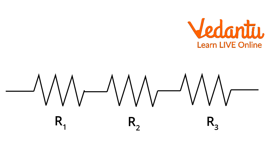
- Total resistance is the sum of all resistances
- Current remains the same in all components
- Total voltage is divided among the components
For resistors $R_1$, $R_2$, and $R_3$ in series, the equivalent resistance is $R_{eq} = R_1 + R_2 + R_3$. The total voltage is the sum of voltages across each resistor. An in-depth analysis of resistance in circuits is available at Understanding Electrical Resistance.
Current and Potential Difference in Parallel Circuits
In a parallel circuit, components are connected across common points, creating multiple branches. The potential difference across each branch is the same, but the current is divided among the branches based on their resistance values.
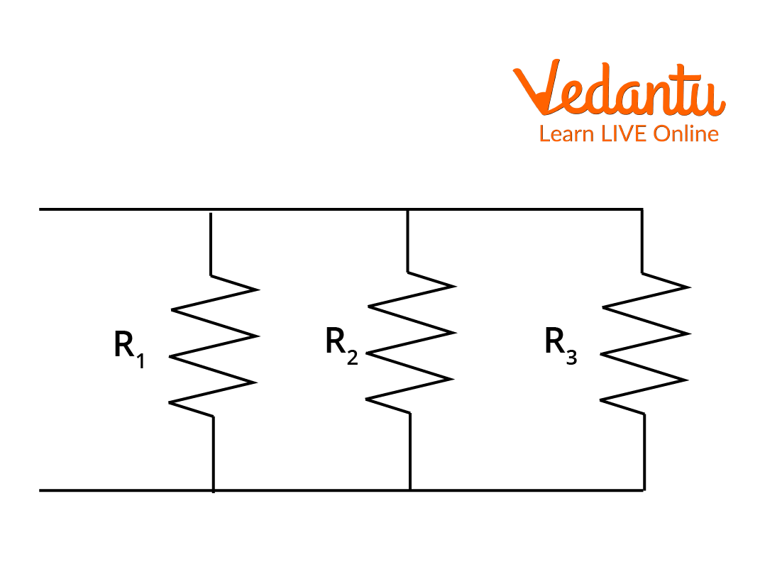
- Voltage is the same across each branch
- Total current is the sum of branch currents
- Reciprocal of total resistance equals sum of reciprocals of individual resistances
If three resistors $R_1$, $R_2$, and $R_3$ are connected in parallel, then $\dfrac{1}{R_{eq}} = \dfrac{1}{R_1} + \dfrac{1}{R_2} + \dfrac{1}{R_3}$. The total current equals the sum of individual branch currents.
Work Done on a Charge and Electric Potential
The work required to move a test charge $q$ from one point to another in an electric field $\vec{E}$ is calculated by integrating the force along the path. The potential at any point is given as the work done per unit charge to bring the charge from infinity to that point.

The mathematical expression is $V = \int_{\infty}^{R} \vec{E} \cdot d\vec{l}$. This concept is foundational for understanding potential difference and energy changes in circuits. More details regarding electric field concepts are in Electric Field Lines Properties.
Solved Example: Series and Parallel Connections
Consider a circuit with a voltage source $V = 2 \mathrm{~V}$ and three resistors: $R_1 = 30~\Omega$, $R_2 = 30~\Omega$, and $R_3 = 30~\Omega$. Two resistors are in series, then in parallel with the third.
| Step | Calculation |
|---|---|
| Series resistance | $30~\Omega + 30~\Omega = 60~\Omega$ |
| Parallel resistance | $\dfrac{1}{R_p} = \dfrac{1}{30} + \dfrac{1}{60}$ |
| Equivalent resistance | $R_p = 20~\Omega$ |
| Total current | $I = \dfrac{V}{R_p} = \dfrac{2}{20} = 0.1~\mathrm{A}$ |
The current flowing through the circuit is $0.1~\mathrm{A}$.
Solved Example: Calculating Voltages and Currents
In a series circuit, current $I = 3~\mathrm{A}$ flows through two resistors, $R_1 = 3~\Omega$, $R_2 = 5~\Omega$.
| Calculation | Value |
|---|---|
| $V_1 = I R_1$ | $3 \times 3 = 9~V$ |
| $V_2 = I R_2$ | $3 \times 5 = 15~V$ |
| Total voltage | $9 + 15 = 24~V$ |
If the $5~\Omega$ resistor is replaced with $10~\Omega$, and the circuit current is $9~\mathrm{A}$, the voltage across each resistor and the circuit is recalculated using $V = IR$ for each component.
Key Points and Summary
Current is the flow rate of electric charge, while potential difference is the energy transferred per unit charge between two points. Their relationship in resistive circuits is specified by Ohm's Law. Analysis of series and parallel arrangements allows prediction of current, voltage, and resistance behavior in different circuits. For practice questions, refer to the Current Electricity Mock Test.
These concepts form the basis for more advanced studies in electric circuits, electrostatics, and the analysis of electrical devices. For additional reading on field effects from charged bodies, see Electric Field From Charged Ring.


FAQs on What Are Current and Potential Difference in Electricity?
1. What is the difference between current and potential difference?
Current is the rate of flow of electric charge, while potential difference, or voltage, is the work done to move a unit charge between two points.
- Current is measured in amperes (A) and represents how much charge passes through a conductor per second.
- Potential difference is measured in volts (V) and indicates how much energy is used to move charges between two points.
- Both are fundamental concepts in electricity and are crucial for understanding circuits.
In summary, current refers to the flow, while potential difference refers to the driving force behind that flow.
2. What is electric current?
Electric current is the flow of electric charge through a conductor.
- Measured in amperes (A).
- Results from the movement of electrons.
- In a circuit, current flows from the positive to the negative terminal.
- Calculated as I = Q/t, where Q is charge (in coulombs) and t is time (in seconds).
This concept forms the basis for understanding all electrical devices and circuits.
3. What is potential difference?
Potential difference (also called voltage) is the amount of work required to move a unit charge between two points in an electric field.
- Measured in volts (V).
- Indicates how much energy electrons gain or lose between two points.
- Given by V = W/Q, where W is work done (in joules) and Q is charge (in coulombs).
The potential difference sets up the push that causes current to flow in a circuit.
4. How are current and potential difference measured?
Current is measured using an ammeter, and potential difference is measured using a voltmeter.
- Place the ammeter in series with the component whose current you want to measure.
- Place the voltmeter in parallel across the two points where you want to measure voltage.
- Both measurements require careful circuit setup for accurate readings.
5. What is the SI unit of electric current and potential difference?
The SI unit of electric current is the ampere (A), and for potential difference, it is the volt (V).
- 1 ampere (A) = flow of 1 coulomb of charge per second.
- 1 volt (V) = 1 joule of work per coulomb of charge.
6. What factors affect electric current in a circuit?
The electric current in a circuit is affected by:
- Potential difference (voltage): Higher voltage increases current.
- Resistance: Greater resistance reduces current.
- Nature of the conductor: Some materials allow more current to flow.
- Length and thickness of the wire: Longer and thinner wires reduce current.
Understanding these factors helps in designing efficient electrical circuits.
7. How are current and potential difference related according to Ohm's Law?
According to Ohm's Law, the current flowing through a conductor is directly proportional to the potential difference across it, provided temperature remains constant.
- Expressed mathematically as V = IR, where:
- V is potential difference (volts)
- I is current (amperes)
- R is resistance (ohms)
- This relationship helps in calculating current or voltage in a circuit.
8. Why does electric current require a potential difference to flow?
A potential difference is needed to provide the energy that pushes electrons through a conductor, causing electric current.
- No current flows without a voltage (potential difference).
- The potential difference acts like a driving force.
- Examples of sources: batteries, cells, generators.
Thus, potential difference is essential for current to exist in any circuit.
9. What are the similarities and differences between current and potential difference?
While both current and potential difference are fundamental to electricity, they have distinct roles.
Similarities:
- Both are scalar physical quantities.
- Both are essential for electric circuits to work.
Differences:
- Current is the flow of charge; measured in amperes.
- Potential difference is the energy per unit charge; measured in volts.
- Current depends on potential difference and resistance.
10. How can you calculate electric current using potential difference?
You can calculate electric current from potential difference using Ohm's Law:
- Formula: I = V/R
- I: Current (in amperes)
- V: Potential difference (in volts)
- R: Resistance (in ohms)
- Substitute values to find current when voltage and resistance are given.
This method is commonly used in circuit calculations.
11. What instrument is used to measure potential difference?
Potential difference is measured using a voltmeter.
- The voltmeter is always connected in parallel across the component or points where voltage is to be measured.
- It gives the reading in volts (V).
12. Why does a bulb glow when connected to a cell?
A bulb glows when connected to a cell because the cell provides a potential difference that pushes current through the filament, causing it to heat up and emit light.
- Flow of electrons produces energy.
- The filament resists current, heats up, and glows.
- Both potential difference and current are necessary for this process.