


An Overview of Class 12 Physics Determining Of Resistance Wire Material Resistivity Using Meter Bridge In Electrical Conductivity Experiment
Samuel Hunter Christie created the Wheatstone bridge in 1833, which was then refined and popularized by Sir Charles Wheatstone in 1843. A Wheatstone bridge is an electrical circuit that balances the two legs of a bridge circuit, one of which contains the unknown component, in order to measure an unknown electrical resistance. The circuit's capacity to deliver incredibly exact readings is its main advantage, in contrast with something like a simple voltage divider which gives some extra resistance to the circuit thus causing errors in measurement. It works similarly to a potentiometer since both help take measurements using a null point.
Table of Contents
Aim
Apparatus required
Theory
Procedure
Observations
Result
Precautions
Lab Manual Questions
Viva Questions
Practical Based Questions
Aim
To find the resistance of a given wire using a meter bridge and hence determine the resistivity (specific resistance) of its material
Apparatus Required
Meter Bridge
Wire About 1m Long (of Material Whose Specific Resistance is to be Determined)
Resistance Box
Rheostat
Galvanometer
Jockey
One-Way Key
Cell or Battery Eliminator
Thick Connecting Wires
Sand Paper
Screw Gauge
Theory
Wheatstone's bridge operates on the same logic as a meter bridge. The device is made up of four resistors P, Q, R and S that are linked together to form the terminals named by letters $ABCD$. A key $K_1$ connects the terminals $A$ and $C$ to two terminals of a cell and another key $K_2$ connects terminals $B$ and $D$ to a delicate galvanometer $G$.
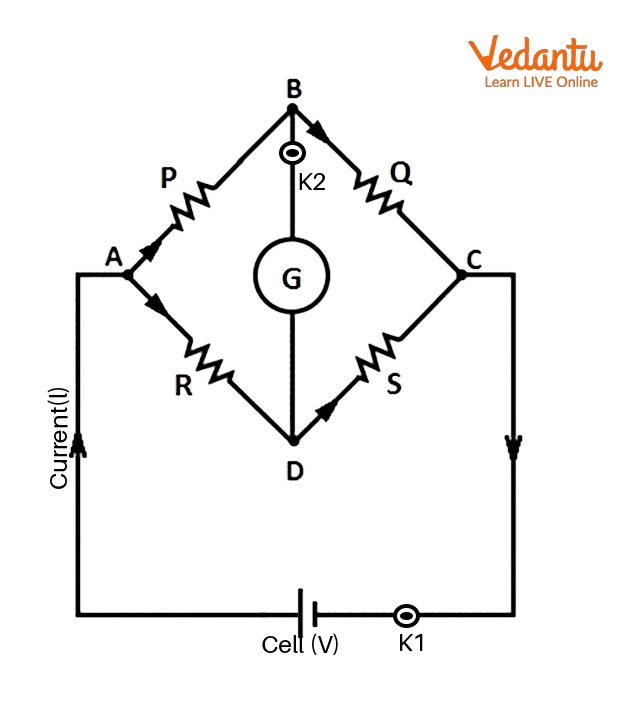
Wheatstone’s bridge
Wheatstone’s bridge is balanced for the condition $\frac{P}{Q} \ = \ \frac{R}{S}$. It is in this condition that the potential difference between points $B$ and $D$ are zero. Therefore, there is no deflection in the galvanometer and a null point is observed. By balancing a Wheatstone’s bridge, one can easily find the one unknown resistance if the other three are known.
A known resistance and the unidentified resistance S are linked in the gaps between A & D and C & D of the meter bridge, respectively. A terminal of the galvanometer G is linked to terminal B. A jockey $J$ that slides along the wire AC is attached to the other terminal of the galvanometer. In order to maintain a consistent potential drop along AC, a source of dc current is linked between A and C through a key $K_1$.
When the null point is obtained, $\frac{P}{Q} \ = \ \frac{R}{S}$ is satisfied.
Also, for a wire, $Resistance \ (R) \ = \ Resistivity \ (\rho) \times \frac{Length \ (L)}{Cross-sectional \ Area \ (A)}$.
Therefore, $R \propto L$. This proves that the resistance of wire $AC$ on which the jockey slides can be related to the length of the wire.
Therefore, $\frac{P}{Q} \ = \ \frac{R}{S} \ = \frac {Resistance \ of \ wire \ of \ length \ DC}{ Resistance \ of \ wire \ of \ length \ DC }$ if $D$ is the null point.
Since $AC \ = \ 100 \ cm$ the above equation can be related as $S \ = \ R \times \frac{l}{100 \ - \ l}$ where, $l$ is length of wire $AD$
Also, from (1) Specific resistance $\rho$ can be related after finding out the resistance, as $\rho \ = \ R \times \frac{A}{L}$ where $A \ = \ \pi \times (radius)^2$
Procedure
Using a screw gauge, determine the wire's average diameter. Divide the obtained diameter into two, in order to get the radius $r$.
Use a piece of sandpaper to remove the insulation from the ends of connected wires. Press each plug to tighten it to the resistance box $(R_{BOX})$.
Connect the circuit as shown in the figure. The wire of unknown resistance but known length should be connected in the gap between A and B.

Circuit diagram
Plug out some resistance from the resistance box. Bring jockey $J$ into touch with terminals $A$, followed by terminal $C$. The galvanometer needle should deflect in the opposite direction on touching each terminal. The null point will be located someplace on the wire $AC$ if the galvanometer exhibits deflection on both sides of its zero mark for these two sites of contact of the jockey. If not, change resistance $R$ so that the null point is at the centre of wire $AC$.
Check the circuit again, especially junctions, for continuity if there is a one-sided deflection.
Change the resistance $R$ and repeat step 4 for four different observations.
Change the resistances $S$ and $R's$ positions, then repeat steps 4 through 6 with the same five $R$ values. Make sure that the same length of resistance-wire $S$ is now in the gap between B and C while switching $S$ and $R$. The interchange takes care of unaccounted resistance offered by the terminals of the meter bridge.
Observation
Length of the wire of unknown resistance -
Measurement of diameter of the wire of unknown resistance -
Least count of the screw gauge (L.C.) -
Zero error of the screw gauge -
Zero correction of the screw gauge -
Observation Table for the Diameter of Wire
Observation Table for Unknown Resistance
Length of wire, $L = $
Radius of cross section of wire, $r = $
Resistivity of material of wire, $\rho =$
Substitute the values in $\rho \ = \ S \times \frac{\pi r^2}{L}$
Where, $L$ is length, $r$ is radius of cross section of wire and $S$ is resistance of wire
Error:
Error in specific resistivity- $\frac{\Delta \rho}{\rho} \ = \ \frac{\Delta S}{S} + 2\frac{\Delta r}{r} + \frac{\Delta L}{L}$
$\Delta r$ and $\Delta L$ are errors in the least counts of the measuring instruments and $\Delta S$ is the maximum error of the values obtained by following equations:
Error in resistance-
$\Delta S_1 \ = \ \left [ \frac{\Delta l}{l} + \frac{\Delta l}{(100 \ - \ l)}\right ] \times S_1$
Similarly, $\Delta S_2 \ = \ \left [ \frac{\Delta l}{l} + \frac{\Delta l}{(100 \ - \ l)}\right ] \times S_2$
Assuming error in resistance from $R_{BOX}$ to be zero, greatest error is:
$\Delta S \ = \ \Delta S_1 \ + \ \Delta S_2$
Result
The provided wire's unknown resistance is determined to be $S \ + \ \Delta S \ =$
The wire is made of material which has a resistivity of $\rho \ + \ \Delta \rho \ =$
Here, $S$ and $\rho$ are mean values whereas, $\Delta S$ and $\Delta \rho$ are maximum errors.
Precautions
1. All of the plugs and connections need to be secure.
2. The jockey should gently be slid over the wire of the meter bridge to avoid altering the cross-section area.
3. Only when taking observations should the plug-in key $(K_1)$ be inserted.
4. The cable should have a null point in the middle of the wire $AC$ (around $30 \ cm$ to $70 \ cm$).
Lab Manual Questions
How will the observations change if the cross-sectional area of the meter bridge wire is not uniform?
What differences in the outcome would there be if the same experiment was carried out with $AC \ = \ 50 \ cm$ wire as opposed to $1 \ m$?
It is possible to locate the null point, or length l, to within $\pm 0.1 \ cm$ (say). How much uncertainty would the result have as a consequence of this error in calculation?
Making use of your observations, plot a graph between $\frac{(100 – l )}{l}$ versus $R$. Find the slope of the graph. What does it represent?
Viva Questions
$R$ and $S$ combinations are often desired to be selected so that the balancing point is close to the center of the meter bridge wire. Why? Is it advisable to have the same order of resistance for $R$ and $S$ to detect the equilibrium point?
Why is the meter bridge named so?
Why is the meter bridge preferred over the ohm’s law circuit to calculate an unknown resistance?
What is the null point? What is its significance?
When readings are not being taken, it is advisable that the key be disconnected to prevent unwanted wire heating. Why? What effects will heating have on the null point? Will its impact be significant?
It is preferred not to measure very high or very low resistances with a meter bridge. Why?
Why are the copper wires used to press the ends of the wire thick?
What are the possible sources of error in the experiment?
How will the observations change if the material used to make the meter bridge wire is not consistent in density?
The scale attached to the wire may not give the precise length. How can this error be minimised?
Practical-Based Questions
When a metal conductor connected to the left gap of a meter bridge is heated, the null point
Shifts towards right
Shifts towards left
Remains unchanged
Remains at zero
Answer: (a)
The null point is obtained in a meter bridge at a distance of $25 \ cm$ from $A$. If the resistance of value $14 \ \Omega$ is shunted to $S$, a null point is observed at $45 \ cm$. Value of $S$ is
$15.364 \ \Omega$
$20.364 \ \Omega$
$25.364 \ \Omega$
$22.364 \ \Omega$
Answer: (b)
We can remove the end error in the meter bridge experiment by
Changing the wire used in meter bridge
Repeating the experiment by changing known and unknown resistance
Taking average value of resistances determined during b.
Both b and c
Answer: (d)
The meter bridge is used to
Measure the electric current in circuit
Measure the potential difference across a resistance
Measure the resistance of a resistor
Measure the power supplied in a circuit
Answer: (c)
If the radius of the wire of the meter bridge is doubled, what will happen to the balancing length?
The balance length will become zero
The balancing length will get doubled
The balancing length will remain the same
The balancing length will be halved
Answer: (c)
On what principle does the meter bridge work?
Potentiometer
Wheatstone’s bridge
Kirchhoff’s law
Ohm’s law
Answer: (b)
Meter bridge can be used to find the resistance of
High value
Moderate value
Low value
All of the above
Answer: (b)
The balance length in a meter bridge experiment is obtained
Extreme left end of wire
Extreme right of wire
At any point on wire
Somewhere in the middle of the wire
Answer: (d)
In a meter bridge the null point is found at a distance of $33.7 \ cm$ from terminal $A$ (known resistance $R$ is connected to the gap near to $A$). If the resistance of $12 \ \Omega$ is connected parallel to unknown resistance $X$ (which is connected to the gap near terminal $B$), the null point is found at $51.9 \ cm$. The value of $X$ is
$13.5 \ \Omega$
$27 \ \Omega$
$25.5 \ \Omega$
$3 \ \Omega$
Answer: (a)
For which of the following pairs of resistors, the balancing length is not $0.25 \ m$ in a meter bridge?
$1 \ \Omega, \ 3 \ \Omega$
$\frac{7}{3} \ \Omega, \ 7 \ \Omega$
$25 \ \Omega, \ 75 \ \Omega$
$2 \ \Omega, \ 3 \ \Omega$
Answer: (d)
Summary
A meter bridge works on the Wheatstone bridge principle and can be used to find out unknown resistances. When this bridge is balanced, the ratio of the resistances is equal, and no current passes through the galvanometer. It works similarly to a potentiometer since both help take measurements using a null point. By balancing a Wheatstone’s bridge, one can easily find the one unknown resistance if the other three are known.
FAQs on Class 12 Physics Determining Of Resistance Wire Material Resistivity Using Meter Bridge In Electrical Conductivity Experiment
1. What is the most important concept to understand when finding the resistance of a wire using a meter bridge for CBSE Class 12 board exams?
The most crucial concept is the principle of the Wheatstone bridge, which the meter bridge uses to compare known and unknown resistances. The balancing condition P/Q = R/S allows you to find the value of the unknown resistance accurately by adjusting for a null point on the wire, and it's directly tied to the types of exam questions asked from this experiment.
2. List out the stepwise procedure most frequently asked in 3-mark board questions for determining the resistivity of a material using a meter bridge.
For board exams, the 3-mark questions usually expect these key steps:
- Connect the unknown resistance wire and a known resistance in the respective gaps of the meter bridge.
- Set up the galvanometer and jockey to detect the null point by sliding the jockey along the meter bridge wire.
- Note the balancing length, apply the formula S = R × l / (100 - l), then use measurements of diameter and length to calculate resistivity ρ = S × πr2 / L.
3. What are the high-weightage errors and precautions that students must mention for 5-mark questions in this experiment?
To secure full marks in 5-mark questions, highlight these errors and precautions:
- Non-uniform wire cross-section leading to end errors.
- Poor electrical connections or loose plugs causing inaccurate readings.
- Incorrect use of the jockey, potentially damaging the wire’s cross-section.
- Always remove the key when not recording observations to avoid heating effects.
- Consistently ensure the null point lies between 30 cm and 70 cm for higher accuracy.
4. Why is it essential to keep the known and unknown resistances in the same order of magnitude during the meter bridge experiment for board practicals?
It is essential because having both resistances in a similar range ensures the balancing point or null point is near the center of the bridge wire. This positioning minimizes the effect of end errors and maximizes accuracy, which is often stressed in CBSE viva and theory questions.
5. What are the possible board traps related to 'end correction' and how can they affect the result?
End correction refers to errors due to non-uniformity or imperfect contact at the ends of the meter bridge wire. This can cause systematic deviations in measured resistance values. Examiners often test your understanding here; recommend interchanging the known and unknown resistances and taking the average value to minimize such errors for the correct board answer.
6. Which formula is expected in exam answers for calculating the resistivity of the wire material, and what SI units must be stated?
The expected board formula is ρ = S × πr2 / L, where S is the measured resistance, r is the radius (in meters), and L is the length (in meters). The resistivity must be expressed in ohm-meters (Ω·m).
7. How can uncertainty in the measurement of length or diameter impact your final resistivity value in long-answer questions?
Any error in measuring the length (L) or the diameter/radius (r) significantly affects the calculated resistivity. Since radius is squared in the formula, a small error in measuring diameter can cause a relatively large error in ρ. In exam answers, always mention combining relative errors as Δρ/ρ = ΔS/S + 2Δr/r + ΔL/L to show understanding of propagation of uncertainty.
8. What is the practical significance of the null point in the meter bridge, and why do boards emphasize its location?
The null point indicates where the ratio of resistances exactly matches the ratio of balancing lengths. Its location (ideally in the center) is emphasized because extreme null points increase experimental error and uncertainty, which directly affects marking for precision in answers.
9. In what situations should the meter bridge experiment not be used for resistance measurement, and how should you justify this in an answer?
The meter bridge should not be used for measuring very high or very low resistances because the sensitivity of the setup decreases and it becomes harder to obtain a clear null point. For full marks, state that at extreme resistance values, errors from connecting wires and contact resistance become significant.
10. How can plotting a graph between (100-l)/l and known resistance R help in verifying the experimental law in 5-mark theoretical questions?
Plotting (100-l)/l versus R should yield a straight line, confirming the linear relation predicted by the meter bridge law S = R × l/(100-l). The slope of this graph corresponds to the unknown resistance S, and including this step demonstrates a complete understanding expected in long-answer board questions.